Inspection and fault detection of the connecting rod and piston group is discussed in the article - "Repair of the connecting rod piston group”.
Let's briefly go over the main features again:
Before installing liners in the cylinder block, if required, the block is well washed and dried.

When replacing liners, new liners are inserted into the cylinder block so that the letter indicating the group of liners is located in the transverse plane.

The sleeve must enter the block completely freely.
The sleeve, installed with a copper gasket in the block, should protrude 0.02-0.1 mm above the surface of the block.
The difference in the protrusion of the liners in the cylinders should be no more than 0.055 mm (this is ensured by selecting the liners in length or by upsetting them with deformation of the copper gasket).

Before installing the sleeve, the place on which the sleeve rests in the block must be smeared with sealant (earlier, oil paint was used during assembly).
After inserting the sleeve into the cylinder block, press the sleeves with light blows.

After installing the sleeves, they must be fixed using suitable bushings, washers and nuts.
Fixation is needed so that when the block is turned over and the pistons with rings are inserted, the liners do not crawl out of the block
About defect detection of the block, corresponding article.
Go to the assembly of the connecting rod and piston group.

Two designations are embossed on the piston head.

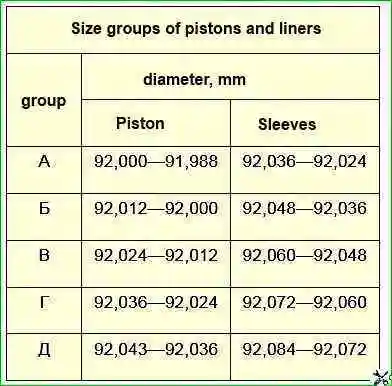
The letter is painted on the block. By this letter, the piston approaches the cylinder.
Of course, if the cylinder-piston group has changed, then this marking is not taken into account.
On the piston head, a Roman numeral indicates the piston group.
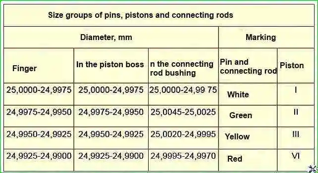
On piston pins, the group number is indicated by paint on the inner surface or on the ends. It must of course match the piston group.

On the connecting rod, the group number is also indicated by paint.
It must either match or be adjacent to the group finger.

The piston pin, lubricated with engine oil, should move with little effort in the connecting rod head, but not fall out of it
We heat the piston to a temperature of about 80˚ C (possible in a water bath) and press in the piston pin.

You can press the finger with a copper or ordinary hammer, through a soft metal mandrel, holding the piston in weight.

After assembly, the tab on the bottom end of the connecting rod should be on the same side as the "Front" lettering on the piston.
The indicative protrusion of the connecting rod of the ZMZ-402 engine is located not on the rod of the connecting rod, but on its cover

Put the retaining rings in the piston.
Checking the piston rings.

Compression rings installed in the cylinder to a depth of 20-30 mm should have a gap in the lock - 0.3-0.6 mm, oil scraper - 0.5-1 mm.

We put the rings on the piston.
We push the lock of the oil scraper ring expander, put it on the piston in the lower groove and reduce the lock.

We put on the lower compression ring with the inscription "TOP" to the piston bottom
Last, put on the top compression ring.
We turn the rings so that the locks of the upper compression rings are on opposite sides of the piston, and the lock of the oil scraper ring is 90˚ to the locks of the compression rings.
When replacing worn or defective sleeves with new and repaired ones, insert them into the block so that the mark on the lower centering part of the sleeve, indicating its group, is located in the transverse plane of the block.
In other cases, before removing the sleeves from the block, they must be marked with serial numbers, as well as mark the position in the block in order to ensure that they are returned to their previous position during assembly.
When replacing pistons, liners, piston pins or connecting rods, mating pairs should be selected at a temperature of parts of 20±3°C. (see size group table below).
When installing new rings on the piston, but keeping the old liners, the protruding shoulder in the upper part of the sleeve should be removed on the machine or with a scraper.
For slightly worn cylinder liners without boring, a set of tinned compression and steel oil scraper rings is provided.
We install the engine block on the stand in an upside down position.
We insert liners with a groove and an oil supply hole into the bed of the main bearings.

We insert two persistent half rings without protrusions on both sides of the central bed.

Turn them with transverse grooves to the cheeks of the crankshaft.o.
We insert two persistent half rings without protrusions on both sides of the central bed

We lubricate the liners and main journals of the crankshaft with engine oil.

We are inserting a new packing - as stated in the article - "Crankshaft repair »

Insert nab the willow in the stuffing holder and place the rubber flags in the stuffing holder
We crimp the packing, as stated in the article - "Crankshaft repair".

We put the crankshaft in the cylinder block.

We install the liners in the main bearing caps, lubricate them with clean engine oil and place them on the crankshaft journals

When installing the cover 2 of the first main bearing, the protrusion of the rear thrust washer 1 must fit into the groove of the cover 2.

Installing the stuffing holder

Use an 8 hexagon wrench to tighten the two nuts securing the packing holder

We tighten the bolts of the main bearing caps in accordance with the tightening torques (see the torque table below)
Turn the crankshaft by hand.
Rotation should be free and uniform without jamming with little effort
The axial play of the crankshaft must not exceed 0.36 mm.
Otherwise, we check the correct assembly, disassemble and troubleshoot.

Installing the front thrust washer 2 on the pins 1, with the anti-friction layer outward

Install the spacer between the crankshaft gear and the front thrust washer.
The spacer washer is installed with the chamfer facing the thrust washer.
Installing the crankshaft gear.
Having pressed the crankshaft gear to the stop, you should check its axial clearance.
The check is carried out as follows: put a screwdriver (knob, hammer handle, etc.) between the first shaft crank and the front wall of the block and, using it as a lever, press the shaft to the rear end of the engine.
Using a feeler gauge, determine the clearance between the end face of the thrust bearing rear washer and the shoulder plane of the first main journal.
The gap should be between 0.125–0.325 mm.

We insert new liners into the connecting rod and its cover.

Lubricate piston rings, liners, cylinder walls and connecting rod journals with engine oil.
We install the device for crimping rings and tapping the rings with a wooden handle of a hammer in a circle.

We correctly orient the piston with the inscription "Front" to the front of the block and insert it into the cylinder according to the order of the numbers.

By tapping the bottom of the piston with the wooden handle of the hammer, we sink it into the cylinder.
On the other hand, we control its correct position relative to the crankshaft journal.

Installing the connecting rod caps

With a head of 15, we tighten the nuts of the connecting rod cover with a moment of 6.8 - 7.5 kgf.m. For tightening, use a torque wrench
Install the camshaft.

Before installing the camshaft, lubricate the journals and camshaft cams, tappets and pushrods with engine oil.
When installing the camshaft, we combine the risk on its plastic gear with the “0” mark on the crankshaft gear.

Installing the camshaft

With a head of 12, we tighten the bolts of the thrust flange through the hole in the gear.

Install the oil slinger on the end of the crankshaft.

Insert the pulley hub key into the crankshaft socket.
Installing the timing gear cover.
In order for the front crankshaft oil seal to sit correctly, it is best to center the cover together with the pulley hub.
Before landing the pulley hub, lubricate the working edge of the oil seal with engine oil.

Using a 13 key, we wrap eight nuts securing the cover
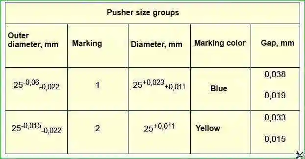
Pushers are selected according to the size of the holes in the block and are divided into two groups (see the table of size groups of pushers).
The crankshaft, flywheel and clutch are balanced as an assembly, so when replacing one of these parts, dynamic balancing should be done by drilling out the metal from the heavy side of the flywheel.
Balancing the crankshaft, flywheel and clutch assembly should not be started if the initial imbalance exceeds 200 cm.
In this case, it is necessary to dismantle the assembly and check the balance of each part separately.
Having pressed the crankshaft gear to the stop, you should check its axial clearance.
Installing the oil pump

We bait and tighten with a key 13 two nuts for fastening the oil pump

Installing a new pan gasket. Lubricate the pan gasket on both sides with sealant

Install the oil pan and tighten the pan nuts crosswise.

A ball bearing 80203 AC9 with two protective washers is pressed into the rear end of the crankshaft.
It is allowed to use a 60203A bearing with one protective washer, while 20 g of Litol-24 grease must be placed in the bearing cavity.
Screw the clutch pressure plate assembly with the casing to the flywheel, having previously centered the driven plate with a mandrel (you can use the input shaft of the gearbox) along the hole in the bearing in the rear end of the crankshaft.
The 0 marks stamped on the pressure plate housing and on the flywheel near one of the holes for the housing mounting bolts must be aligned.
Lubricate the joints of the lower flange of the cylinder block with the timing gear cover and the packing holder with Elastosil 137-83 glue-sealant or UN-25 paste.
Tightening torques for threaded connections of the ZMZ-402 engine
Connection name / Tightening torque kgcm
- Spark Plugs 3.0-3.5
- Cylinder head nuts 8.3-9.0
- Nuts for connecting rod bolts 6.8-7.5
- Main bearing cap nuts 10.0-11.0
- Flywheel nuts 7.6-8.3
- Nuts for fastening the clutch housing to the cylinder block 2.8–3.6
- Crankshaft bolt 17-22
- Clutch pressure plate bolts 2.0-2.5
- 1.5-3.0 exhaust manifold inlet pipe mounting nuts
- Sump nuts 1.2-2.0
- Cylinder head bolts:
- - preload 4.0–6.0
- -final tightening 13.0–14.5
- Nuts for connecting rod bolts 6.8-7.5
- Main bearing cap bolts 10.0 - 11.0
- Flywheel bolts 7.2-8.0
- Clutch housing bolts 4.2-5.1
- 10.4-12.0 crankshaft bolt
- Clutch pressure plate bolts 2.0-2.5
- Camshaft cover bolts 1.9-2.3
- Camshaft sprocket bolts 5.6-6.2
- Valve cover bolts 0.5–0.8
- Inlet pipe mounting nuts, clutch booster mounting bolts 2.9-3.6
- Coolant pump pulley bolts, cylinder head front cover, chain cover, thermostat housing 2.2-2.7
- Stuffing box mounting bolts, oil pan 1.2–1.8
- Exhaust manifold nuts 2.0-2.5
- Main bearing cap nuts 12.5-13.6
- Nuts for connecting rod cap bolts 6.8-7.5
- Nuts for connecting rod cap bolts 6.8-7.5
- Nuts for fastening the racks of the axis of the rocker arms 3.5–4.0
- Oil filter mounting fitting 8.0-9.0
- Oil filter 2.0-2.5
Size groups of pistons and liners

Size groups of pins, pistons and connecting rods

Pusher size groups


