To overhaul the engine, we disassemble the cylinder block.
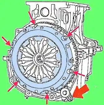
Install the flywheel retainer Mot582-01 or Mot1677 (see the arrow in Fig. 1).
Remove the pressure and clutch discs.
It is recommended to mark the mutual position of the clutch basket and the flywheel so that there are no problems with their balancing during assembly, this is especially true when reassembling the same parts.
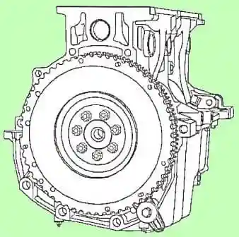
Remove the flywheel (see Fig. 2).
It is recommended to mark the position of the flywheel on the crankshaft flange.
These two parts are balanced as an assembly, so a different relative position may upset the balance, especially if the repair or replacement of these parts is not provided.
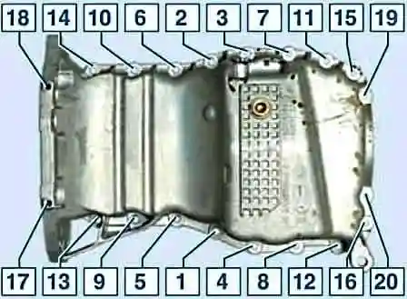
Unscrew and remove the engine oil pan (see Fig. 3).
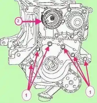
Remove the timing belt tensioner (see Fig. 4).
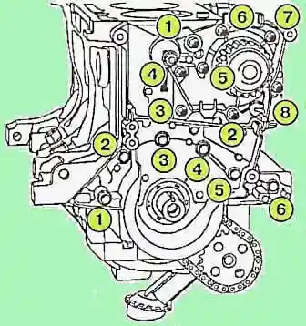
We unscrew the bolts and remove the water pump (Figure 5)
Remove the engine block front cover.
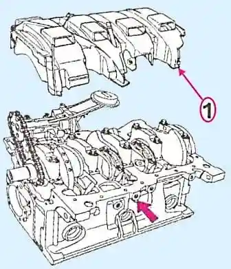
Remove the oil level sensor (see the arrow, Fig. 6), oil separator (sump).
Mark the top of the connecting rod and its cap with a marker.
In this case, it should be taken into account that the bearing shells do not have a bent guide mustache, and there is a groove under the mustache on the connecting rod and serves to orient the connecting rod relative to the piston.
For ease of assembly, mark the side of the connecting rod towards the flywheel.
Note.
Do not use a center punch or engraver to mark the top and end of the connecting rod, as this may lead to subsequent destruction of the connecting rod during operation.
Use a permanent marker.
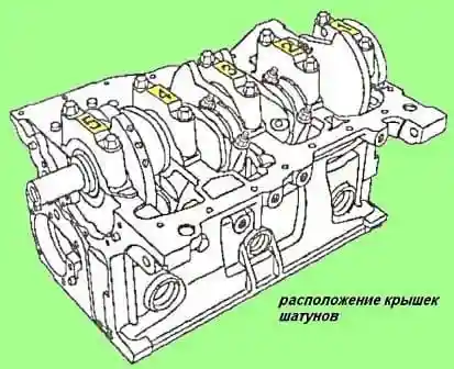
Unscrew the connecting rod cap nuts (see Fig. 7) and carefully remove the connecting rod caps with bearing shells.
Remove pistons with connecting rod assemblies, oil pump drive chain and oil pump.
Set aside the second connecting rod bearing half shells.
Note.
Pistons with connecting rods are removed towards the block head, while wrapping tape around the lower connecting rod head so as not to scratch the cylinder walls.
Remove the crankshaft main bearing caps (bearing caps are numbered 1 to 5) (see fig. 7).
Remove the main bearing shells from the caps.
Note. Be sure to mark the main bearing shells and crankshaft bearings, as different sizes of shells can be installed on the same engine.
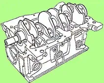
Remove the crankshaft (see fig. 8) and remove the lower bearing half shells.
Removing the piston cooling nozzles
The nozzles are used to supply a jet of oil from below to the bottom of the pistons, this enhances the cooling of the pistons during operation, which made it possible to reduce their weight and increase the effective engine power.
The only way to remove the nozzles is by destroying them, otherwise you won't be able to create a support surface for the puller.
When assembling, you will have to replace the nozzles with new ones.
On the other hand, without removing the injectors, it is impossible to clean the engine oil supply channels to the injectors.
With poor maintenance and cheap motor oil, this can lead to mad reducing or even stopping the supply of engine oil to cool the pistons, which is fraught with melting of the pistons during operation.
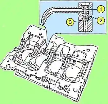
Ream the body of the piston cooling nozzle from above with a drill with a diameter of 7 mm, it is necessary to remove the rolled edge holding the plug (1) (see Fig. 9).
Do not remove the ball (3) so that the chips do not get into the oil channel (see fig. 9).
- - Remove plug (1) and spring (2).
- - Remove metal filings with a brush.
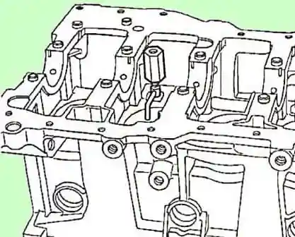
Put adapter Mot1485 or Mot1485-01 into the nozzle (see fig. 10).
- - Screw the Emb880 inertial puller into the adapter.
- - dismantle the injectors using an inertial puller.
Cleaning the bottom of the engine
Clean the following assemblies with DECAPJOINT to dissolve any adhering gasket residue:
- - cylinder block;
- - crankshaft;
- - engine oil pan;
- - front cover of the engine block;
- - crankshaft main bearing caps.
Apply the compound to the surface to be cleaned, wait approximately 10 minutes, then remove it with a wooden spatula.
Do not clean the seating surfaces of aluminum parts with sharp-edged tools.
Do not allow cleaning agent to come into contact with paintwork.
Carry out cleaning carefully, do not allow dirt to enter the channels that supply oil to the hydraulic pushers and camshafts (channels are located in the cylinder block and block head), and oil outlet channels.
If this requirement is not observed, the oil supply channels may become clogged, which will lead to a quick engine failure.
Blow out all oil channels with compressed air, in case of obstruction of the channel, clean it with a soft wire and rinse with special products.
Next, we prepare all the details for inspection and fault detection.
After that, we assemble the engine. These points will be discussed in the following articles.


