
Install the cylinder block on the engine assembly stand.
Assemble and prepare the piston group
Prepare the crankshaft for assembly
Assembling the 470.63 engine
First, you need to lay the crankshaft.

To do this, unscrew the side mounting bolts of the brackets (main bearing caps) (Fig. 1).

Unscrew the lower mounting bolts of the brackets (main bearing caps) (Fig. 2)

We take out the brackets and lay them out in order (Fig. 3).
We wipe the seats of the main bearings.

We put the upper main bearings with a groove in the middle (Fig. 4)

Lubricate with engine oil and install the tappets in the block sockets (Fig. 5)

Lubricate the upper main bearings with a thin layer of engine oil (Fig. 6)

Put the crankshaft in the cylinder block.
Put the crankshaft so that the counterweight of the crankshaft of the first cylinder looks down relative to the engine sump (then it fits better in place) (Fig. 7)

Insert the lower main bearing shells into the brackets (caps of the main bearings), lubricate the shells and install the brackets so that the bearing locks match (Fig. 8).
Tighten the lower bolts of the brackets

Insert steel-aluminum half rings into the grooves of the rear main bearing so that the side with the grooves fits against the thrust ends of the shaft, and the whisker fits into the groove on the rear main bearing cover.
Pre-tighten the main bearing bolts to a torque of 94.2 ÷ 117.7 Nm (9.6 ÷ 12 kgf.m)

Start tightening from the middle main bearing (Fig. 10), in the order 3-4-5-2-1.
Finally tighten the main bearing cap bolts to a torque of 206÷230.5 Nm (21÷23.5).
Screw in and tighten the M12 block tie bolts, ensuring a tightening torque of 80.4÷90.2 Nm (8.2÷9.2 kgf.m).
When tightening with a torque wrench, the resistance should increase smoothly, without jerks. Count the moment when moving the key
After tightening, the crankshaft should rotate freely from the force of the hand applied to the flywheel mounting pins, the axial clearance in the thrust bearing should be at least 0.05 mm.
For ease of installation of the piston group, turn the block on the stand to a vertical position.
We begin installation with the eighth cylinder

Insert the upper liner connecting rod, we lubricate it a thin layer of engine oil (Fig. 11), and lubricate the cylinder with a thin layer of engine oil.
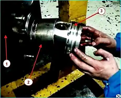
Using the device for installing the piston group, insert the connecting rod with the piston into the cylinder block, ensuring different positions of the ring locks so that the locks do not coincide on the same axis with the piston pin.
Using the wooden side of the hammer, carefully tap the piston, ensuring the correct position of the bolts and connecting rod liner.

Insert the liner into the connecting rod cover, lubricate the connecting rod and install it so that the bearing locks match (Fig. 13).
Tighten the connecting rod cap fastening nuts.
Tightening torque of connecting rod cap bolts with M12 thread to elongation by 0.25 ÷ 0.27 mm.
Reinforced design bolts with M13 thread – 117.7 ÷ 127.4 Nm (12 ÷ 13 kgf.m).
After this, insert the connecting rod with the piston into the fourth cylinder.
Turn the crankshaft and insert the piston with the connecting rod into the 7th and 3rd cylinders.

In the same way, we insert the remaining pistons with connecting rods and tighten them with a torque wrench (Fig. 14), to the torque specified above.
Turn the crankshaft several times.

")
")
")
")
")
")
")
")