Repair of a connecting rod-piston group is carried out with capital or partial engine repair, when it is necessary to change the parts of the SPG.
Of course, if the engine has already been removed, it is desirable to carry out overhaul, since the engine will still have to shoot.
Disconnect battery cables
We drain the oil from the lubrication system
Remove the wizard probe and the oven tube
Remove the pallet crankcase and gasket
Remove the piston cooling nozzles
We merge the cooling fluid
Remove the head of the cylinder block
Turn the crankshaft so that the pistons are below the nagar deposition zone, which is located above the zone of movement of the piston rings.
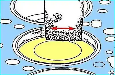
To remove a car, use fine-grained abrasive bar with fibrous structure and solvent.
Apply the cylinder number on the bottom of the piston.
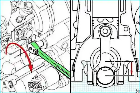
We rotate the crankshaft so that the piston is at the bottom of the dead point for removing the connecting rod
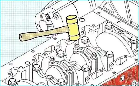
We unscrew the connecting rod bolts, but do not remove the bolts.
Hell with a rubber head, knock on the connecting rod bolts to notice the covers.
If the engine is installed on the engine with the bottom head of the discontinuous type, exhibit caution when removing the lid to avoid damage to the contact surfaces of the connecting rod or cover.
In case of damage to the contact surfaces in the rupture zone, be sure to replace the connecting rod and its cover to reduce the probability of engine damage. Violation of the assembly rules may damage the connecting rod.
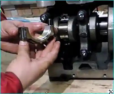
Remove the Bolts of Shatun
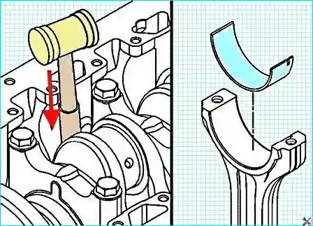
Remove the rod cover
We remove the lower liner of the connecting rod bearing.
Pour the piston assembled with the cylinder rod.
Remove the upper liner of the connecting rod bearing.
Battle liners cannot be reused.
The piston and the rod assembly should be installed in that cylinder from which they were removed to ensure accurate fit of the accuracy of the surfaces if the parts are reused.
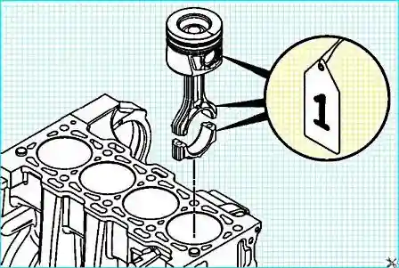
It is necessary for each piston assembly to attach a tag with the cylinder number.
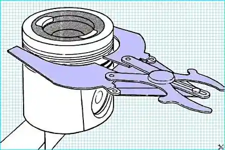
Using the Piston Rings Expander (Catalog No. 3823137), remove the piston rings.
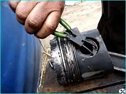
Remove the retaining rings from the piston grooves
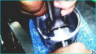
Remove the piston finger and remove the connecting rod.
Clean and check the pistons and piston fingers.
Check the state of the rods
Installation of a connecting rod-piston group
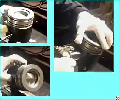
Install the spring ring in the piston finger groove on one side of the piston
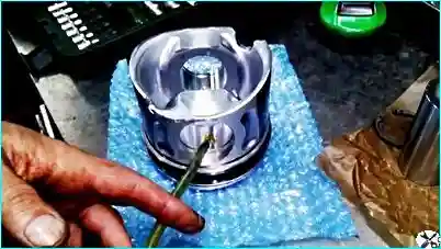
Lubricate your finger and holes under it with clean engine oil
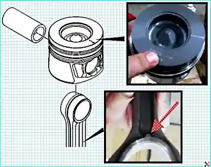
When assembling the piston and connecting rod, you need to follow the right orientation.
On the surfaces of the rods there are three notches that must be addressed towards the front of the engine
On the pistons there is an arrow applied to them for this purpose.
We set the pistons on the connecting rods (heating the pistons to install the finger is not necessary).
Insert your finger into the piston and connecting rod.
Install the second locking ring.
Install piston rings
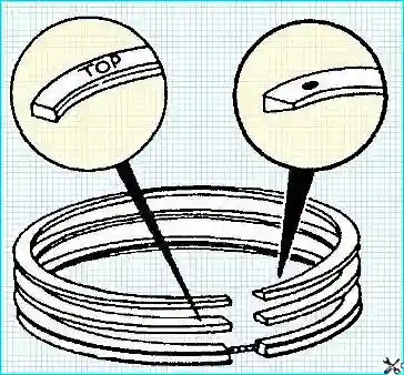
On the upper surface of the compression rings there is a TOR label, or a label of their manufacturer, for example "point".When assembling, the tags must be drawn up.
Mascarming (Lower) Ring is set to any side.
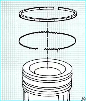
The oil surcharge must be installed so that the clearance of the spring expander is opposite the ring of the ring.

Using the expander (catalog number 3823137), we set the piston rings to the piston.
Type and installation location Ring Determine its profile.
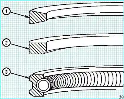
- - 1 - upper compression piston ring;
- - 2 - intermediate piston ring;
- - 3 - oil-chamming ring.
Clean the cylinder block before assembly and all the details.
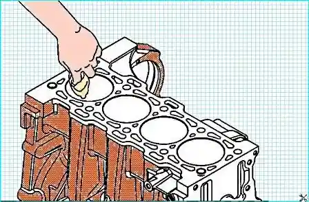
Check the cylinder block for the presence of defects.
Make sure that there are no dirt and foreign particles on the connecting rods and the back of the liners.
Do not lubricate the opposite side of the rod bearings.
Install the top insert into the connecting rod.
The ledge of the bearing liner should get into the slopes of the connecting rod.
The edge of the liner must be flush with the surface under the lid.
If the engine is installed on the engine with the lower head of the discontinuous type, then the lower and upper bearing liners are not interchangeable.
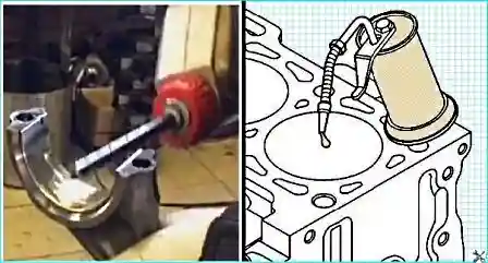
Clean oil for assembly works, the number according to the directory 3163087, or its analogue, lubricate the inner surface of the liner.
Lubricate the wall of the cylinder with engine oil.
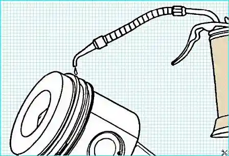
Grease rings and skirts with pistons with clean engine oil.
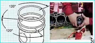
Turning the rings, we have their locks as shown in the picture.The lock of each ring should not be opposite the piston ring or castles of other rings.
Incorrect location of the castles of the rings will lead to a violation of the tightness of the cylinder.
The device for compressing the rings, the number in the catalog 4919373, compress the rings.
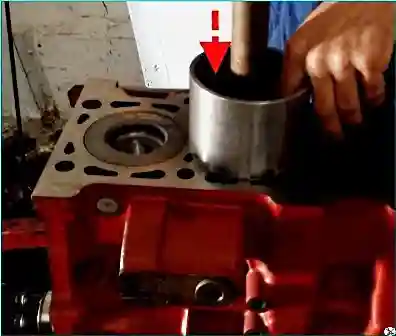
Turn the crankshaft so that the connecting rod neck of the connecting rod is at the bottom of the dead point.
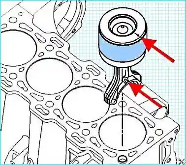
Be sure to follow the orientation of the piston assembled with the connecting rod when it is installed.
By placing the "Front" label (forward) and / or the arrow on the top surface of the piston in the direction of the front of the engine, insert the connecting rod into the cylinder to the contact to compress the piston rings with the upper surface of the cylinder block.
Press the fixture for compressing the piston rings to the cylinder block.
Push the piston through the device to the cylinder.
Move the piston until the upper ring is fully included in the cylinder.
If the piston does not move freely, remove it and check if there is no broken or damaged rings.
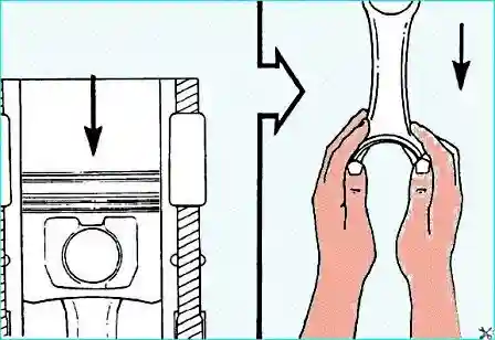
Carefully pushing the piston into the cylinder, directing the connecting rod to the rod cerv.
Be careful not to damage the crankshaft neck.
Install the liner in the rod cover.
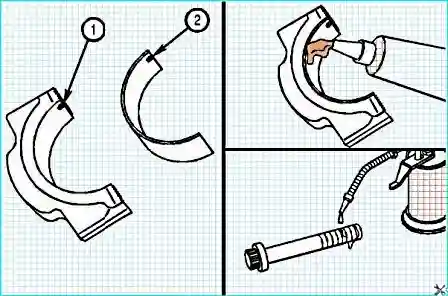
The protrusion "2" of the liner should get into the groove "1" of the lid.Lubricate the inside the inner surface of the liner.
The rooms on the connecting rod and the lid should be the same, the piston must be installed in the appropriate cylinder.
Rooms on the connecting rod and cover must be on one side of the connecting rod to reduce the likelihood of engine damage during its operation.
Install the cover and rod bolts.
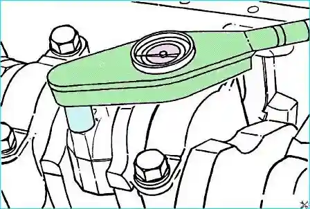
With a dynamometric key, tighten the connecting rod cap bolts.Using the bolt rotation method to a certain angle at the end of the tightening, alternately tighten the connecting rod bolts:
- the first stage of the tightening - 34 nm;
- the second stage - rotate 60˚ counterclockwise;
- the third stage - tighten with a moment of 34 nm;
- Fourth stage - rotate an angle 60˚ clockwise.
We measure the side gap between the connecting rod and the crankshaft crank
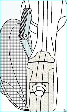
The side clearance should be - 0.100 -0.004 - 0.35 +0.014 mm
We measure the spelling of the piston over the upper surface of the cylinder block.This operation is necessary only after repair or replacing the piston, crankshaft, connecting rod or cylinder block.
We measure the speech using the depth gauge (No. 3823495 according to the catalog).
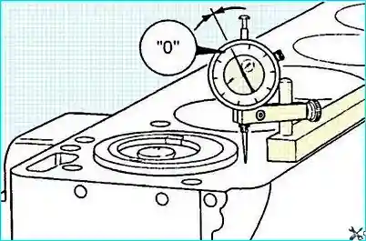
Install the dial indicator on the top surface of the cylinder block and exhibit it to zero.
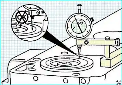
Move the indicator directly above the piston finger, not allowing its transverse deviations.
Do not touch the protrusion of the electroplating surface indicator.
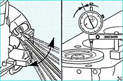
Turn the crankshaft so that the piston is in the upper dead point.
Turning the crankshaft in different directions, determine the maximum indicator reading.
Record the measurement results.
Piston speaker must be: 0.034 -0.001 - 0.260 +0.010 mm
If the protrusion protrusion does not match the norm, you need to check the correctness of the selection and processing of parts.
Check the free rotation of the crankshaft after installing the connecting rods.
If the crankshaft does not rotate freely, check how connecting rod bearings and their size.
After the operations completed, we collect all the details in the reverse order in accordance with the technology.


