
Select your language

Removal and installation of the instrument cluster

Removal and installation of the instrument cluster

The instrument cluster is not repairable; if the instrument gauges fail, the cluster is replaced as a complete unit.

We disconnect the negative battery terminal.
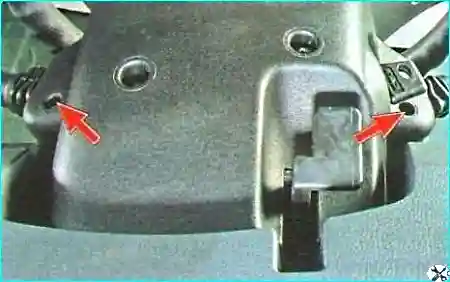
Steering column shroud securing screws
Fig. 1. Steering column shroud securing screws.

We unscrew the two screws joining the upper and lower parts of the steering column shroud.
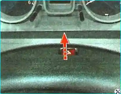
Removal of the upper part of the steering column shroud
Fig. 2. Removal of the upper part of the steering column shroud.

We pull upwards and remove the upper part of the shroud.
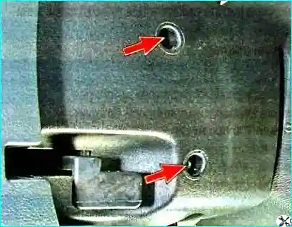
Unscrewing of the lower part of the shroud securing screws
Fig. 3. Unscrewing of the lower part of the shroud securing screws.

We unscrew the two screws securing the lower part of the shroud to the steering column.
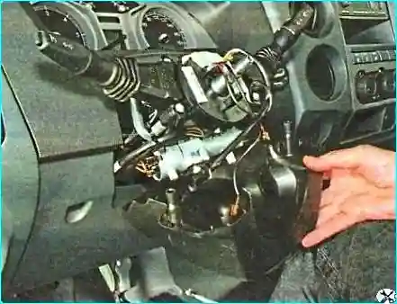
Removal of the lower part of the steering column shroud
Fig. 4. Removal of the lower part of the steering column shroud.

We remove the lower part of the shroud.
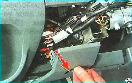
Removal of the lower decorative trim of the instrument panel
Fig. 5. Removal of the lower decorative trim of the instrument panel.

We remove the lower decorative trim of the instrument panel.

Prising up the left edge of the decorative trim
Fig. 6. Prising up the left edge of the decorative trim.

We prise up the left edge of the decorative trim and release it from the instrument panel.

Location of the decorative trim fasteners (view from the inside)
Fig. 7. Location of the decorative trim fasteners (view from the inside).

Location of the fasteners of the instrument cluster decorative trim (view from the inside).

Disconnection of the wiring connector from the coolant preheater timer
Fig. 8. Disconnection of the wiring connector from the coolant preheater timer.

If the vehicle is fitted with a coolant preheater, we disconnect the wiring connector from its timer.

We unscrew the four screws securing the instrument cluster to the instrument panel.

Unscrewing of the instrument cluster securing screws
Fig. 9. Unscrewing of the instrument cluster securing screws.

We extract the instrument cluster from its recess in the instrument panel and move it aside by the length of the wires.

Flipping up of the wiring connector retaining clip
Fig. 10. Flipping up of the wiring connector retaining clip.

We flip up the wiring connector retaining clip.

Disconnection of the connector from the instrument cluster socket
Fig. 11. Disconnection of the connector from the instrument cluster socket.

We disconnect the connector from the cluster socket.

Removed instrument cluster
Fig. 12. Removed instrument cluster.

We remove the instrument cluster.

Important: we install the instrument cluster in the reverse order.