


The fuel rail accumulates fuel and distributes it among the lines of the individual injectors.
A sensor is installed in the rail to monitor the pressure created in it by the high-pressure pump.
The signal from this sensor is used by the ECM module to regulate the delivery of the high-pressure fuel pump.
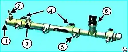
In addition, there is a pressure relief valve in the common line.
It acts as a safety valve, releasing excess pressure if the pressure in the fuel line exceeds the set level.
Fuel drained from the common high-pressure line is returned to the fuel tank through the drain line.
When unscrewing and disconnecting the rail, the following must be taken into account:
- all open fuel lines must be plugged immediately after removal to prevent dirt ingress;
- the fuel pressure sensor must only be removed if it is to be replaced; if the sensor has been removed, it must be replaced without fail (the rail is supplied with the pressure sensor installed);
- before removal, mark the location of the fuel supply line to the injectors.
The internal channels of the rail may only be cleaned with contact cleaner catalogue no. 3824510 or its equivalent.
Before disconnecting the lines, clean the unions.
The spanners used when disconnecting the lines must be clean.
Disconnect the negative battery terminal.
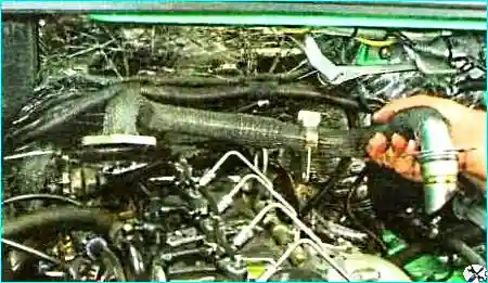
Remove the recirculation system pipe.
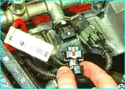
Press the retainer and disconnect the wiring connector from the fuel pressure sensor in the rail.
Unscrew the nut securing the high-pressure line to the rail.
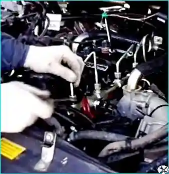
Unscrew the nut securing the high-pressure line to the injector.
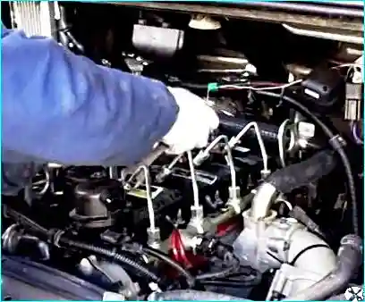
Remove the line and unscrew the lines of the other three injectors.
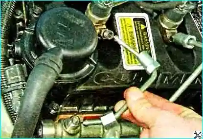
Unscrew the nut securing the high-pressure supply line to the rail and disconnect the line from the rail.
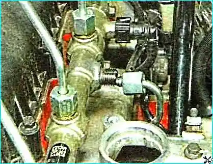
Squeeze the retainer and disconnect the return line end fitting from the rail.
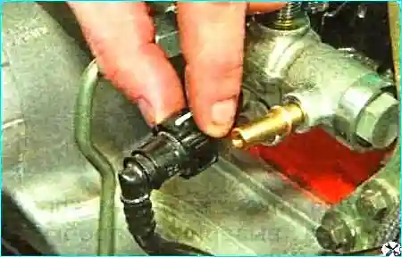
Unscrew the three bolts securing the rail to the cylinder head.
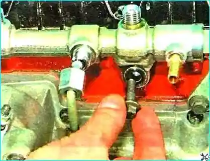
Remove the rail.
After removing and flushing the rail, check the condition of the unions installed on the rail for the absence of cracks or scratches.
Install the fuel rail on the engine.
Connect all fuel lines.
Bleed the system (article — Fuel system maintenance).
Insert and tighten the rail securing bolts (tightening torque: 24 N·m).
Tighten all fuel lines (tightening torque: 27 N·m).
Materials used and recommendations
Clean the internal channels of the rail only with contact cleaner catalogue no. 3824510 or its equivalent. Before disconnecting the lines, clean the unions, and the spanners used must be clean. Plug all open fuel lines immediately after removal to prevent dirt ingress.
Remove the fuel pressure sensor only if it is to be replaced; if the sensor has been removed, it must be replaced (the rail is supplied with the pressure sensor installed). Before removal, mark the location of the fuel supply line to the injectors to ensure correct assembly. After removing and flushing the rail, check the condition of the unions for the absence of cracks and scratches. Observe the tightening torques: rail securing bolts — 24 N·m, fuel lines — 27 N·m. After assembly, bleed the fuel system and check the tightness of the connections.