
Mechanical three-shaft gearboxes of three types are installed on UAZ vehicles:
- - four-speed, with synchronizers only in III and IV gears;
- - four-speed, with synchronizers in all forward gears;
- - five-speed, with synchronizers in all forward gears.
Four-speed gearboxes are interchangeable, but they can have different sizes of input shaft splines (for different clutch drive discs).
Five- and four-speed gearboxes are interchangeable complete with their transfer cases and cardan shafts. When installing
A five-speed gearbox instead of a four-speed one also requires completion of the body floor hole for the transfer case levers. Nodes and
parts of different gearboxes are not interchangeable.
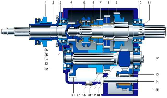
Four-speed gearbox with synchronizers in III and IV gears: 1 - clutch release clutch; 2, 6 - primary and secondary shafts; 3 - retaining ring or nut; 4.10 - front and rear bearings of the secondary shaft; 5 - synchronizer clutch; 7, 8, 9 - gears III, II and I gears; 11 - retaining ring; 12 - a bolt of fastening of the back bearing of an intermediate shaft; 13 - bearing of the reverse gear block; 14 - axis of the reverse gear block; 15 - reverse gear block; 16 - spacer sleeve; 17.18 - gears of II and III gears of the intermediate shaft; 19 - drain plug; 20 - crankcase; 21 - intermediate shaft drive gear; 22 - intermediate shaft bearing; 23 - nut; 24 - intermediate shaft; 25 - plug; 26 - input shaft front bearing cap
The four-speed, not fully synchronized gearbox consists of a one-piece cast iron crankcase in which the primary, secondary and intermediate shafts are mounted on ball bearings.
The front end of the secondary shaft rests on a full complement roller bearing in the bore of the rear end of the input shaft, and the rear end rests on a double-row ball bearing, along which the box is centered
gear and transfer box.
The countershaft drive gears, as well as Ⅱ and Ⅲ gears are helical, constant mesh.
Splines are installed on the intermediate shaft of gear Ⅱ and gear Ⅲ.
Bronze bushings with holes and cellular knurling are pressed into the holes of the gears of the 2nd and 3rd gears of the secondary shaft to improve lubrication.
To supply oil to the bushings, radial holes in the gears and helical grooves on the shaft are used.
Third and fourth gears are engaged by moving the inertial synchronizer clutches on the output shaft.
The driven spur gearⅠ of the transmission moves along the splines of the output shaft.
First gear is engaged by moving the driven gear along the splines of the secondary shaft back until its teeth mesh with the teeth of the drive gear.
Moving the driven gear Ⅰ gear forward engages the 2nd gear (its spline ring is connected through the 1st gear gear to the output shaft).
In addition, the driven gear has a middle position. In this case, it is used to engage reverse gear.
The reverse gear block is located on a cage needle bearing sliding along an axis pressed into the crankcase.
When the gear set is moved along the axis forward, its large gear engages with the drive gear of the first gear, and the small gear engages with the driven gear on the secondary shaft.
At the same time, the primary and secondary shafts begin to rotate in different directions, and the car moves backward.
The gear shift mechanism consists of a cover in which three rods with forks are installed, a shift lever with a spring, and a spring-loaded fuse that prevents accidental reverse gear engagement.
Fixation of the included gears is carried out by spring-loaded balls included in the holes on the rods.
The locking device in the form of two plungers and a pin on the stem of III and IV gears does not allow switching on two gears at the same time.
The gearbox is lubricated with gear oil poured into the crankcase.
For filling and draining oil, filler and drain holes are used, closed with plugs with conical threads.
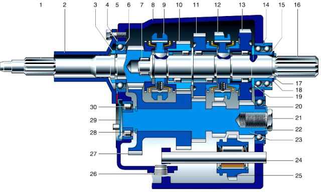
Four-speed gearbox with synchronizers in all forward gears: 1.16, 23 - primary, secondary and intermediate shafts; 2 - front bearing cover; 3 - special nut or retaining ring; 5 - gasket; 6 - input shaft bearing; 7 - front p output shaft bearing; 8 - crankcase; 9 - synchronizer clutch of III and IV gears; 10, 11 - gears of III and II gears; 12 - synchronizer clutch of I and II gears; 13 - gear of the 1st gear; 14 - locking plates; 15 - bearing; 17 - retaining ring; 18 - washer; 19 - spacer ring; 20 - intermediate shaft bearing; 21 - special bolt; 22 - special washer; 24 - axis of the reverse gear; 25 - intermediate reverse gear; 26 - drain plug; 27 - block of gears for the drive of the intermediate shaft and III gear; 28 - retaining ring; 29 - plug; 30 - roller bearing
The four-speed, fully synchronized transmission differs from the one described in that:
- - the inclusion of all forward gears is carried out by moving the clutches of two inertial synchronizers mounted on the secondary shaft;
- - gears of I, II and III gears - helical, constant mesh, mounted on the secondary shaft on double-row roller bearings with plastic cages;
- - the front end of the intermediate shaft rests on a radial roller bearing;
- - the driven gear of the intermediate shaft drive and the leading gear of the III gear are made in the form of a block pressed onto the smooth part of the intermediate shaft;
- - leading helical gears of I, II gears and a spur reverse gear are made integral with the intermediate shaft;
- - reverse gear is engaged by moving the reverse intermediate gear until it engages with the spur gear of the intermediate shaft and the ring gear of the synchronizer clutch of Ι and II gears.
In addition, this box has other gear ratios in all gears except IV gear.
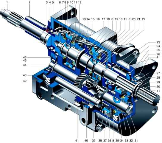
Five-speed gearbox: 1 - input shaft; 2 - bearing cover; 3 - cuff of the input shaft; 4 - retaining ring; 5 - ball bearing of the primary shaft; 6 - roller bearing of the secondary shaft; 7 - spline crown of the input shaft: 8 - blocking ring; 9 - clutch of the synchronizer of III-IV gears; 10 - clutch hub; 11 - key; 12 - splined crown of the gear of the third gear; 13 - third gear gear; 14 - gear bushing; 15 - second gear gear; 16 - crankcase; 17 - second gear bushing; 18 - splined ring gear of the second gear; 19 - synchronizer clutch II-I gears; 20 - splined ring gear of the 1st gear; 21 - gear 1st gear; 22 - bushing gear 1st gear; 23 - roller bearing of the secondary shaft; 24 - output shaft sleeve; 25 - driven gear V gear; 26 - crankcase V transmission; 27 - double-row ball bearing of the secondary shaft: 28 - slotted washer; 29 - retaining ring; 30 - secondary shaft; 31 - bolt; 32 - disc spring, 33 - support ring; 34 - drive gear V gear; 35 - splined crown of the drive gear of the 5th gear; 36 - synchronizer spring; 37 - synchronizer cracker; 38 - clutch synchronizer V transmission; 39 - ball bearing of the intermediate shaft; 40 - roller bearing of the reverse gear; 41 - reverse gear; 42 - axis of the reverse gear; 43 - gear block for the drive of the intermediate shaft and III gear; 44 - intermediate shaft; 45 - roller bearing of the intermediate shaft; 46 - bearing cover
The five-speed gearbox is designed on the basis of a fully synchronized four-speed gearbox and differs in that the fifth gear case is bolted to the rear wall of its crankcase.
Crankcases are centered with two locating sleeves. The secondary and intermediate shafts are made longer
A double-row angular contact ball bearing of the secondary shaft is located in the rear wall of the fifth gear housing, and an additional radial roller bearing is installed in the bore of the rear wall of the gearbox.
At the rear end of the intermediate shaft, on a double-row needle bearing, a fifth gear (large) helical gear with an inertial synchronizer is installed. The driven (small) gear of the fifth gear is located on the splines of the secondary shaft.
When the fifth gear is engaged, the secondary shaft rotates faster than the primary, therefore the fifth gear is called overdrive.
Thanks to its use, the number of revolutions of the crankshaft is reduced at high vehicle speeds, which increases engine life and saves fuel
Lubrication of the fifth gear parts is carried out from the common oil bath of the gearbox.
To reduce oil leakage, a rubber cuff is installed in the cover of the input shaft of the five-speed box.
Changing the oil in the gearbox
Drain the gearbox oil immediately after the trip, before it cools down
We recommend combining this operation with changing the oil in the transfer case
Installing the car for inspection ditch or lift

Using a 12 hexagon, unscrew the drain plug, substituting a container of at least two liters, and drain the oil

If the used oil is dark in color * or metal particles are noticeable in it, we flush the gearbox, for which we wrap the plug, cleaning its magnet from steel chips
The oil may have a dark color not only as a result of wear of parts, but also initially, for example, with the addition of molybdenum disulfide or graphite

Unscrew the filler plug with a 12 hexagon
Pour about one liter of a mixture of gear or engine oil (70-80%) with kerosene or diesel fuel (20-30%) into the box with an oil syringe and wrap the filler plug
Having switched on the first gear, we start the engine for 2–3 minutes
Completely drain the flushing oil (draining time is at least 5 minutes).
We clean the drain plug again and wrap it.

Using an oil syringe, fill the gearbox with fresh gear oil in a volume of 1 liter (1.3 liters for a five-speed gearbox)
We wrap the filler plug.
During operation, it is possible to throw some of the oil from the gearbox into the transfer case through the output shaft bearing
In this case, the oil level in the gearbox may drop (up to 8 mm) relative to the lower edge of the filler hole
It is not necessary to add oil in this case
Possible gearbox failures and troubleshooting
Noise in the gearbox, knocks
- Loose fastening of the gearbox to the clutch housing and transfer case
Tighten loose connections
- Wear of gear teeth and bearings
Replace Parts
- The oil is too thin or its level is too low
Change oil or top up
- Wear or destruction of parts
Disassemble and repair the gearbox
Difficulty shifting
- The clutch is not completely disengaged ("leads"), as a result of which the synchronizer blocks the gear shift
Adjust the clutch and its release drive
- Wear of synchronizer parts or ball exit from the socket
Replace worn parts
- Bending of the forks and other parts of the shift mechanism
Straighten deformed parts or replace them
Self disengagement of the gear when the car is moving
- Weakening of fit on centering surfaces as a result of wear or crushing of parts
Replace parts. Choose a synchronizer hub with a clutch
- Bearing wear
Replace bearings
- Misalignment of parts due to deformation of shift forks
Straighten forks or replace with new ones
- Wear of gear rims and synchronizer couplings
Replace worn parts
- Axial clearance of shafts and gears against wear or loosening of fasteners
Tighten fasteners, worn out - replace
Oil leak
- Increased oil level in the gearbox
Set required oil level
- Oil foaming due to poor quality or water ingress
Change the oil
- Loose crankcase plugs
Tighten plugs
- Loose or damaged parts with gaskets (side cover, shift lever support, transfer case connector, driveshaft front cover, intermediate shaft cover)
If tightening the fasteners does not fix the leak, replace the gasket by applying a thin layer of sealant to it
- Cracks in the crankcase or covers
Replace damaged parts
- Rod hole plugs falling out
Install new stubs and emboss

")
")
")
")
")
")
")
")