In the article, we will consider disassembling the generator and replacing the elements of the generator
We prepare the car for the task and remove the generator, as described in the previous article
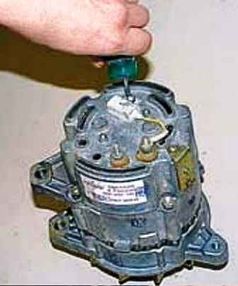
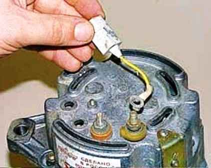
We unscrew the screw securing the capacitor with a screwdriver and remove the capacitor
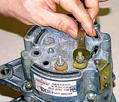
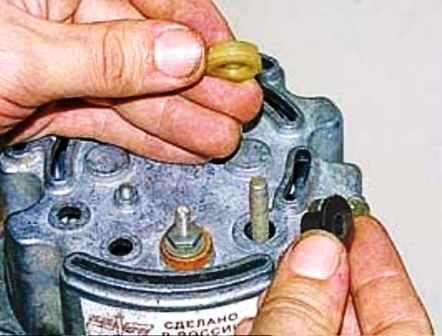
We unscrew the “+” output nut with a 10 key and remove the insulating sleeves from the output
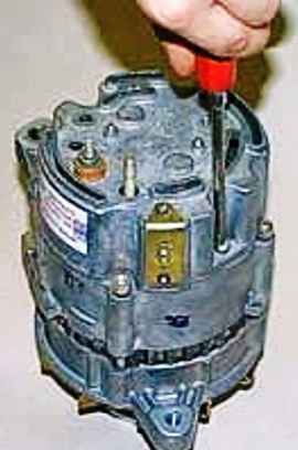
Using a screwdriver, unscrew the two screws securing the rear cover cover
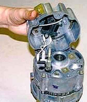
Raise the cover
Remember the order of connecting wires
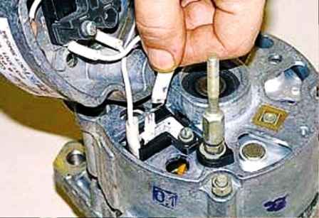
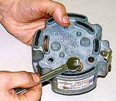
Disconnect wires from terminals
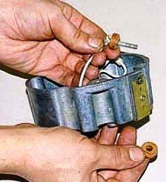
We unscrew the nut with a 10 key and remove the terminal with an insulating sleeve from the cover
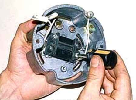
Using a Phillips screwdriver, unscrew the two screws securing the voltage regulator
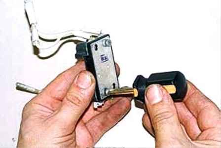
We take out the regulator and unscrew the two screws securing the contact group
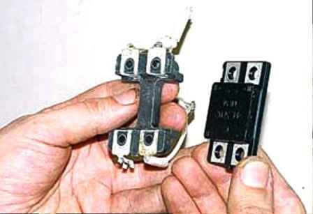
Remove the voltage regulator
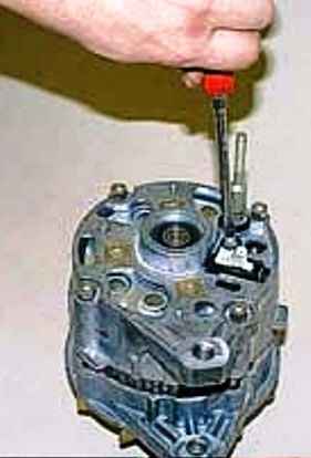
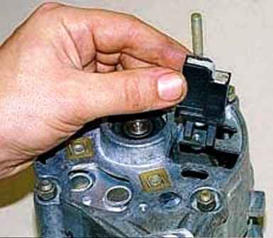
Unscrew the screw securing the brush holder with a screwdriver and remove it
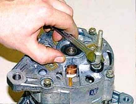
We unscrew the “+” output extension with a 10 key
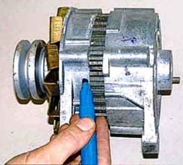
For assembly, mark the position of the covers and the stator of the generator
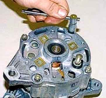
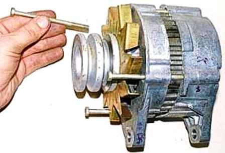
We unscrew the nuts of four bolts with a head for 10 and take out the bolts tightening the generator covers
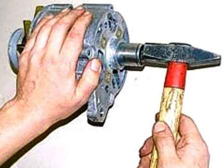
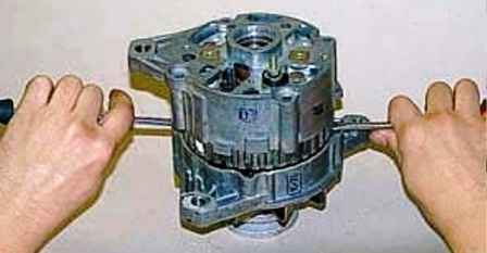
With a mandrel or head with a diameter of 32 mm, we cut it with light blows, and then with two screwdrivers we pry and remove the back cover with the stator from the front cover
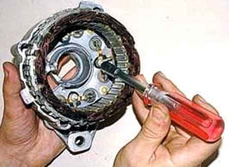
We unscrew the three nuts securing the stator leads to the rectifier unit with a head 8
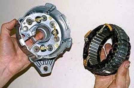
Remove the stator from the cover
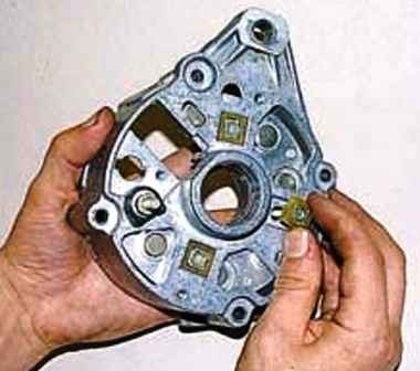
We remove three contact bolts from the cover
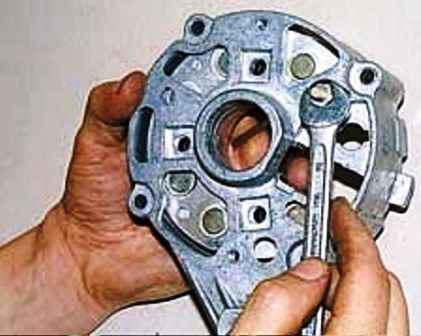
We unscrew the nut of the output "+" of the generator with a key 10
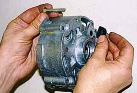
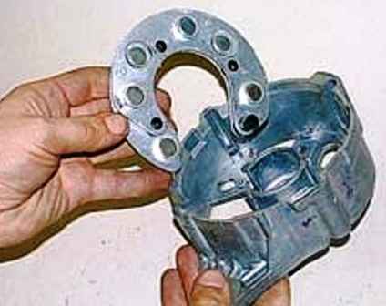
We take out the contact bolt with an insulating insert and take out the rectifier unit
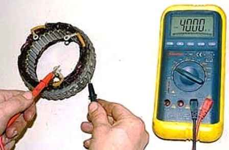
Megaohmmeter check the stator windings for a short circuit
In the absence of a short circuit, the resistance tends to infinity
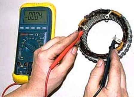
Check the winding for wire breaks
In the absence of a break, the winding resistance will be close to zero
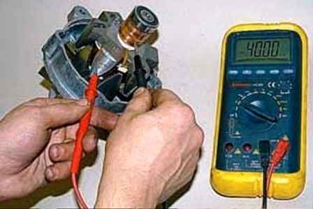
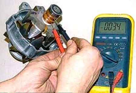
In the same way, we check the rotor for the absence of a short circuit of the winding to ground and a break in the windings
We replace the defective rotor and stator
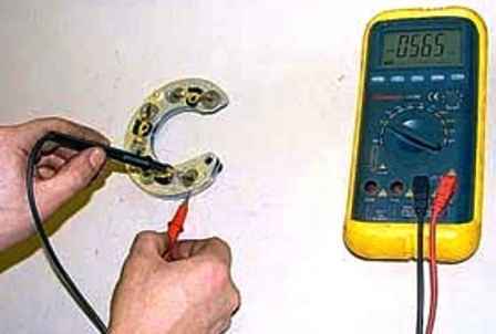
We check the valves of the rectifier unit with an ohmmeter, for this we connect the probes of the device to the terminals of the valves.
The valve (diode) has one-way conduction
A defective one usually passes current in both directions
In case of failure of one of its elements, we replace the rectifier unit as an assembly.
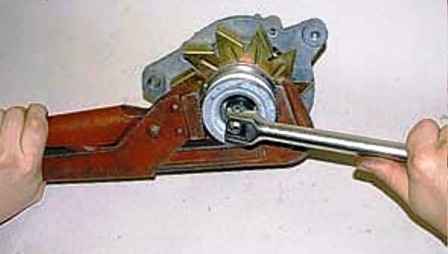
Unscrew the head on the 19 pulley nut, holding the pulley with a pipe wrench
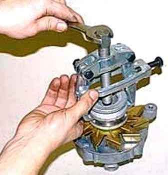
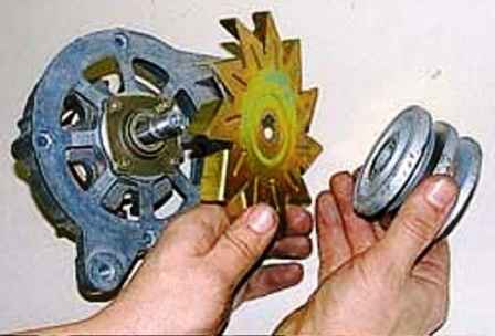
We pull the pulley off the rotor shaft with a puller and remove the pulley with the impeller
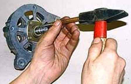
Knock the key out of the shaft with a beard
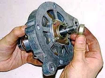
Remove the spacer
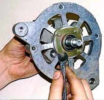
Using the “8” key, we unscrew the four nuts securing the bearing caps.
When assembling, the connections were locked - the ends of the screws were crumpled.
If the screws turn when unscrewing, it is necessary to re-tighten the nuts and file or saw off the crumpled ends with a hacksaw
In this case, new screws may be required during assembly
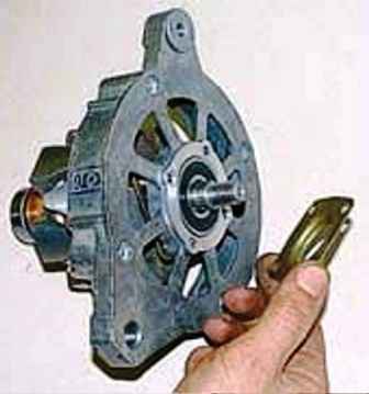
Remove the outer bearing cover
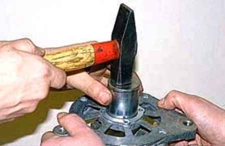
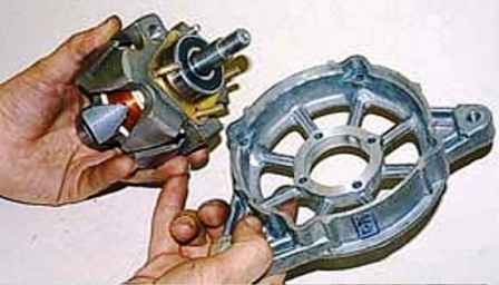
Using a mandrel or a head with an outer diameter of 40 mm, we knock out the bearing from the cover along with the rotor
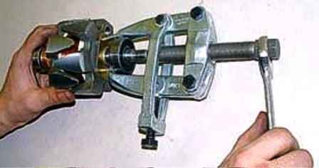
We press the bearing from the rotor shaft with a puller
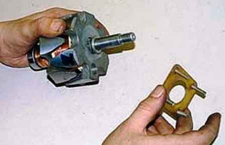
Remove the inner bearing cover with screws and spacer
Remove the rear rotor bearing with a puller similar to the front one
We clean all parts from dirt and coal dust, blow them with compressed air
Wipe heavily oiled contact rings with a cloth soaked in gasoline and clean with fine emery cloth
In case of severe wear, we grind the rings or replace the rotor.
Assemble the generator in the following order
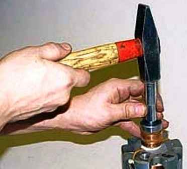
With a suitable bushing or high head for 12, we press the rear bearing onto the rotor shaft
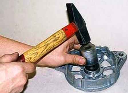
We install the front bearing in the generator cover, acting on the outer ring
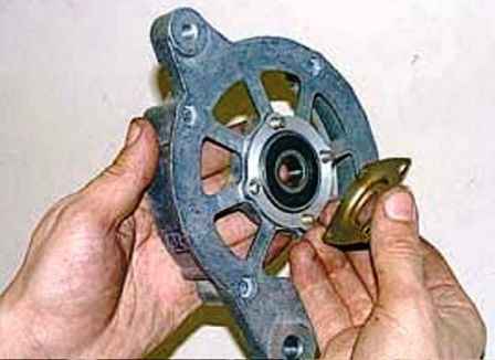
Installing the bearing caps with screws
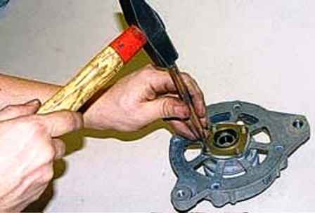
Putting a pulley under the cover, we lock the nuts, crushing the ends of the screws with a chisel
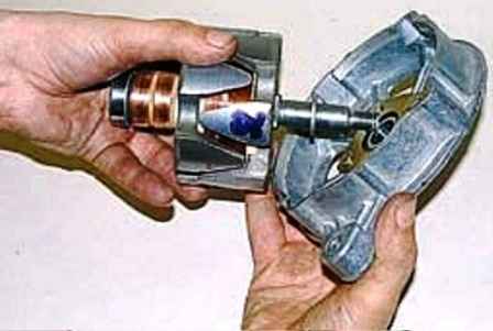
Install a spacer bushing on the generator shaft
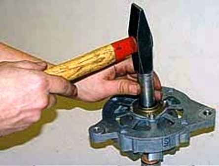
With a suitable piece of pipe or a head for 17, we press the bearing together with the cover onto the shaft
Next, we assemble the generator in reverse order
After assembly, the rotor should rotate, without jamming and clicking, and have no play


