
Steering - safety, consists of a steering wheel, a non-adjustable steering column with one or two cardan joints, a steering mechanism and a steering gear
The steering can be equipped with hydraulic booster
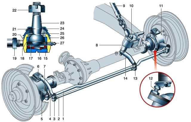
Steering (with a worm-roller mechanism): 1 - trapezoid transverse link; 2 - tie rod bipod; 3 - hinge of the steering knuckle lever; 4 - steering knuckle lever; 5 - right rotary fist; 6 - king pin grease fitting; 7 - trapezoid lever; 8 - steering mechanism of the worm-roller type; 9 - steering shaft; 10 - adjusting nut; 11 - left rotary fist; 12 - bolt-turn limiter; 13 - bipod hinge; 14 - bipod; 15 - plug; 16 - spring; 17 - heel; 18 - cracker; 19 - thrust nut; 20 - thrust tip; 21 - protective ring; 22 - finger nut; 23 - finger; 24 - cap; 25, 26 - spherical washers; 27 - grease fitting
The steering gear consists of a bipod, a bipod rod, steering knuckle levers, a steering trapezium rod and trapezoid levers
The rods are located in front of the front axle and are connected to the bipod and levers by spherical self-clamping collapsible hinges with tapered shanks
Trapezoid linkage, adjustable in length, which allows you to change the amount of convergence of the front wheels
The bipod thrust is also adjustable, which is necessary to ensure the correct mutual position of the bipod and knuckles
The rotation of the steering wheel is transmitted to the steering shaft.
The steering gear bipod through the bipod rod and the lever turns the right wheel pivot arm. The trapezoid rod connects the steering knuckles of the wheels through the trapezoid levers and synchronizes their rotation.
Three types of steering mechanisms can be installed on cars
The worm-roller type steering mechanism consists of a crankcase in which a globoidal worm is mounted on tapered roller bearings, which engages with a double-ridged roller
The roller rotates on ball angular contact bearings mounted on an axle pressed into the head of the bipod shaft
When the steering shaft is turned, the worm rotates, and the roller, rolling along it, turns the bipod shaft mounted in the crankcase on a radial roller bearing and a bronze bushing. The mechanism is adjusted with a screw at the end of the bipod shaft.
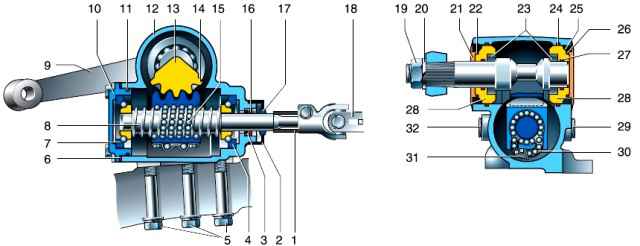
Steering gear type screw-ball nut-rail-sector: 1 - bushing; 2 - protective cover; 3 - cuff; 4, 7 - screw bearings; 5 - bolts; 6 - gasket; 8 - screw; 9 - bipod; 10 - cover; 11 - ring; 12 - crankcase; 13 - shaft-sector; 14 - sector teeth; 15 - balls; 16 - washer; 17 - stuffing box; 18 - fork; 19 - nut; 20 - spring washer; 21 - cover; 22 - ring; 23 - sector bearings; 24, 25, 26, 27 - sealing rings; 28 - ring of the shaft-sector support; 29 - filler plug; 30 - ball chute; 31 - overlay; 32 - drain plug
The steering mechanism of the screw-ball nut-rack-sector type consists of an aluminum crankcase in which a screw is installed on angular contact bearings
The screw encloses a ball nut that has a helical groove on the inside and rack teeth on the outside. Balls are placed between the nut and the screw
When the screw rotates, the balls roll along the helical groove, and the nut moves along the screw.
The rack teeth turn the sector shaft mounted in the crankcase on two cylindrical roller bearings without a cage. A steering arm is fixed on the conical splines of the sector shaft
The engagement of the rail with the sector shaft is adjusted by turning the eccentric cages of the sector shaft bearings
The screw with ball nut and balls are matched to each other and, if necessary, can only be replaced as an assembly.
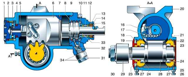
Steering gear with hydraulic booster (distributor with spool shaft): 1 - adjusting nut; 2, 9, 21 - sealing rings; 3,10,11 - bearings; 4, 7, 8, 23 - seals; 5 - screw; 6 - rack-piston; 12 - distributor housing; 13 - cuff; 14, 18 - retaining rings; 15 - protective ring; 16 - ball guide; 17 - balls; 19, 22 - lower and upper protective covers; 20 - crankcase; 24 - rollers; 25 - locknut; 26 - locking bolt; 27 - supports of the shaft-sector; 28 - shaft-sector; 29 - bipod; 30 - nut; 31 - bolt-fitting; 32 - check valve; 33 - spool shaft; 34 - copper washers
The power steering mechanism is installed in two types, differing in the type of distributor (with a spool shaft or a rotor shaft).
These mechanisms are not interchangeable in the place of attachment of the steering shaft joint fork.
The power steering mechanism is designed like a ball screw, but its rack is made in the form of a piston with a seal, and a valve shaft (rotor) of the distributor is located inside the screw shaft.
Instead of the cover of the upper bearing of the propeller, a hydraulic distributor is installed.
The hydraulic cylinder is made directly in the cast-iron crankcase of the steering mechanism and the piston-rack with seal divides it into two cavities
Depending on the direction of rotation of the steering shaft, the corresponding cylinder cavity is connected via a hydraulic distributor to the supply or discharge line of the system
At the same time, the working fluid (oil) supplied by the pump puts pressure on the piston and moves it, turning the sector shaft, thereby “helping” the driver.
Prolonged operation with a non-working hydraulic booster leads to increased wear of the steering mechanism.
Even short-term operation of the hydraulic booster pump without oil is unacceptable! In this case, remove the pump drive belt
On a vehicle equipped with a hydraulic booster, a pump and a reservoir of the hydraulic booster system are additionally installed.
All units are connected by rubber hoses.
The high pressure hose has union fittings at the ends.
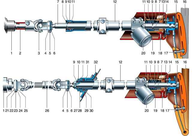
Steering column with one and two hinges: 1 - steering mechanism; 2 - bushing; 3 - hinge; 4,21,25 - washers; 5 - bolt; 6, 15, 24 - nuts; 7 - steering column shaft; 8, 9, 30 - retaining, protective and sealing rings; 10 - spacer sleeve; 11 - bearings; 12 - column; 13 - the upper casing of the column; 14 - steering column switch; 16 - steering wheel; 17.18 - screws; 19 - lower casing of the column; 20 - ignition switch; 22 - wedge; 23 - cotter pin; 26 - cardan shaft; 27 - adjusting nut; 28 - special column support nut; 29 - support washer; 31 - column support; 32 - sealant
The steering column shaft is equipped with two cardan joints and a spline connection.
If the hydraulic booster system fails, the steering remains operational, but the force on the steering wheel increases.
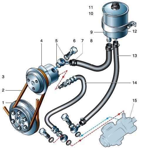
Power steering system: 1 - crankshaft pulley; 2 - belt; 3 - pump pulley; 4 - hydraulic booster pump; 5 - copper washers; 6 - bolt-fitting; 7 - collar; 8 - inlet hose; 9 - tank; 10 - cover; 11 - cap nut; 12 - tank bracket; 13 - outlet hose; 14 - discharge hose; 15 - power steering
The hydraulic booster pump is of rotary (gate) type, mounted on a bracket in the upper part of the cylinder block and driven by a V-belt from the crankshaft pulley
Safety and flow valves are mounted in the pump housing.
The safety valve protects the pump from overloads by connecting the discharge cavity with the suction cavity.
The flow (bypass) valve limits the flow of fluid into the system when the pump shaft speed increases beyond a certain one.
The hydraulic booster reservoir serves as a reservoir for the working fluid, as well as for cooling and cleaning it from foreign particles and wear products of the pump and steering gear
The reservoir with a steel body is mounted on a bracket under the hood at the front left.
A filter element is built into the tank, which cleans the liquid from particles larger than 45 microns.
During the operation of the hydraulic booster, all fluid constantly circulates through it
We replace the filter element and fluid after 100 thousand kilometers or every two years of operation, as well as during repairs
As a working fluid, special oil of grades "P" or "A" is used, poured into the hydraulic booster system in a volume of 1.1 liters.
Steering mechanisms without hydraulic booster are lubricated with gear oil poured into the crankcase.
Power steering gears are lubricated with working fluid.
Checking the technical condition of the steering
Turning the steering wheel, we set the front wheels in the position of the rectilinear movement of the car.
We put a screwdriver on the instrument panel with the tip to the rim of the steering wheel at its upper point.
Turn the steering wheel in both directions until resistance appears (the wheels do not turn).

Being guided by the tip of the screwdriver, we mark with chalk on the rim the boundaries of the free play of the steering wheel
Using a tape measure, we measure the distance along the wheel rim between the marks
If the steering wheel free play is greater than 40 mm, which corresponds to a steering wheel turn of 10°, it is necessary to make sure that the increase in free play is not caused by wear of the tie rod joints and cardan joints, play of the front wheel bearings, and loosening of the bipod nut , nuts of hinge pins, wedges of the cardan shaft and other fasteners
To do this, we check the tightness of the nuts and bolts of the steering, tighten them if necessary.
The nuts of the ball joints of the steering rods and the propeller shaft of the steering must be securely tightened and cottered

When turning the steering wheel, we make sure that there are no backlashes in the ball joints of the rods.
Similarly, we check the backlash in the cardan joints of the steering shaft.
We replace defective parts with worn hinges
If, after eliminating the above backlashes, the free play exceeds the allowable limits, we adjust the steering gear
Possible steering problems and solutions
Increased steering wheel free play (more than 10°)
- Clearance in the pivot joints of the steering rods
Tighten the hinge cap, if necessary, replace worn parts
- Loosening of the steering knuckle lever
Tighten the knuckle arm stud nuts
- Loose fastening of ball pins of steering rods
Unpin and tighten the pin nuts
- Loosening the bipod fastening nut
Tighten the nut
- Loosening the bolts of the steering gear to the frame side member
Tighten bolts
- Wear or misalignment of steering gear
Adjust engagement, replace worn parts if necessary
- Wear or violation of the adjustment of the tightening of the bearings of the worm (screw)
Adjust bearings or replace worn parts
- Ball screw wear
Replace steering gear
- Fork loosening
Tighten the mount, if necessary, replace worn parts
Axial movement of the steering wheel on the shaft or axial movement of the worm (screw) felt on the steering wheel
- Loose steering wheel nut
Tighten the nut
- Loose tightening of the steering shaft joint pinch bolts
Tighten the bolt nuts
- Violation of the adjustment of the tightening of the bearings of the worm (screw)
Adjust bearings
- Wear of the bearing or cones of the worm (screw bearings)
Replace worn parts
Self-excited angular oscillation of the front wheels
- low tire pressure
Check and set normal pressure
- incorrect front wheel alignment
Check and adjust front wheel alignment
- increased wheel imbalance
Balance wheels
- the adjustment of the clearance in the engagement of the steering mechanism is broken
Adjust mesh clearance
Radial movement of the steering column shaft, felt on the steering wheel
- Destruction or wear of steering column bearings
Replace bearings
- Incorrect position of the expansion sleeve in the bearing as a result of overtightening of the column attachment to the bracket and its displacement downwards or the exit of the retaining rings of the bearings from the grooves
Pull the column up and tighten the nuts, reinstall the expansion sleeves and retaining rings
Steering gear stuck
- Incorrectly adjusted side clearance in the engagement of the steering gear
Adjust hooking
- Large wear parts
Replace worn parts
Squeaks and clicks in engagement
- lack of oil in the steering gear
Check the tightness of the cuff and fill the crankcase with oil
- Destruction of working surfaces of parts
Replace worn parts
- Increased clearance in the engagement of the steering mechanism
Adjust hooking
Oil leak from crankcase
- wear of cuffs or sealing rings
Replace cuffs and rings
Squeaking at the top of the steering column
- lack of lubrication in the steering column bearing
Remove the steering wheel and grease the bearing
High Steering Force (Power Steering)
- Pump drive belt slippage
Adjust belt tension
- The presence of air in the system due to low oil level in the reservoir
Fix leaks, add oil, bleed the system
- Incorrect adjustment of the gearing or tightness of the bearings of the steering screw
Adjust steering gear
- Contamination of the flow or safety valves of the pump
Rinse valves
- Faulty pump
Replace pump
Increased noise during operation of the hydraulic booster pump
- Insufficient oil level
Check the system for leaks, add oil
- Insufficient tension of the pump drive belt
Adjust belt tension
- Presence of air in the system
Bleed the system

")
")
")
")
")
")
")
")