


The technical condition of the belt should be checked at every vehicle service.
The belt replacement interval, regardless of its condition, is 60,000 km of mileage or four calendar years, whichever comes first.
A broken belt can lead to significant engine repairs.
The engine pistons and valves can suffer significant damage.
The valves either break off or bend, and the pistons are destroyed. The connecting rods are also damaged.
When inspecting the belt, attention should be paid to ensuring there are no cracks, cuts or delaminations.
The surface of the belt must not have traces of oil.
On the F4R and K4M engines, the pulleys do not have setting marks, so special tools are required to set the camshafts to the TDC position of the first cylinder, and a special pin to lock the crankshaft at TDC of the first cylinder.
The tools can, of course, be made yourself according to the figures given in this article.
We prepare the vehicle to carry out the task.
We place it on a lift or an inspection pit.
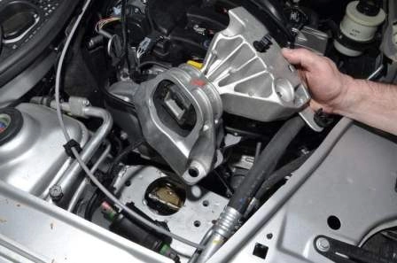
We remove the right-hand powertrain mount, to do this:
We place a jack under the sump, via a wooden or rubber block.
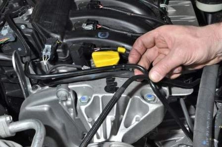
We withdraw the fuel pipes from the holders located on the mount bracket.
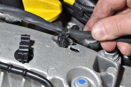
We withdraw the wiring harness holder from the opening in the mount bracket.
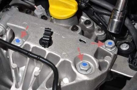
Using a 16 mm socket, we undo the three bolts securing the mount bracket to the upper timing cover.
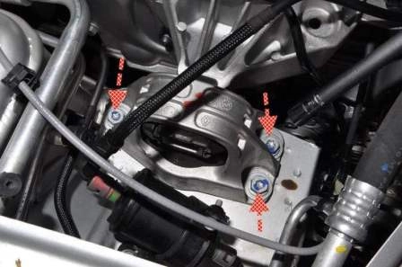
We undo the three bolts securing the mount to the body.
We remove the right-hand mount.
We remove the right-hand mudshield (article — Removal of engine protection, wheel arch liners and mudflaps).
Checking and replacing the belt on the K4M 1.6 l engine
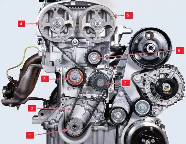
The location and installation diagram of the belt are shown in figure 6.
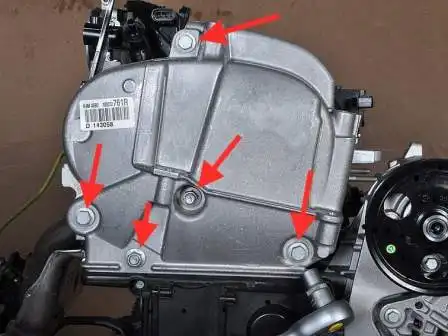
Using a 13 mm socket, we undo the three bolts and two nuts securing the upper timing cover.
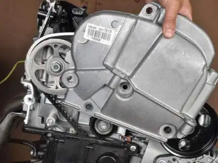
We remove the upper cover.
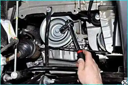
Using an 18 mm socket, we turn the crankshaft clockwise and inspect the timing belt.
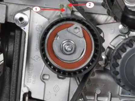
With normal belt tension, indicator 1 should coincide with the recess of indicator 2 on the tensioner roller.
If the movable indicator is offset relative to the fixed indicator, we tighten the belt.
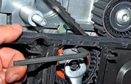
Using a 13 mm spanner, we loosen the nut securing the tensioner roller and, using a 6 mm hex key, turn the roller clockwise, tensioning the belt until the indicators coincide.
Holding in this position, we tighten the roller securing nut.
To replace the belt, we remove the auxiliary drive belt (article — Checking and replacing the auxiliary drive belt).
We remove the upper timing cover.
We engage fifth gear, and an assistant presses the brake pedal.
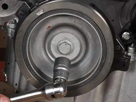
Using an 18 mm socket, we undo the bolt securing the auxiliary drive pulley.
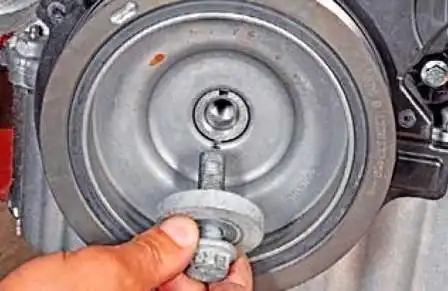
We withdraw the bolt with the washer.
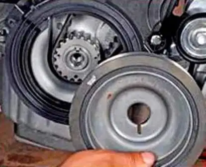
We remove the auxiliary drive pulley.
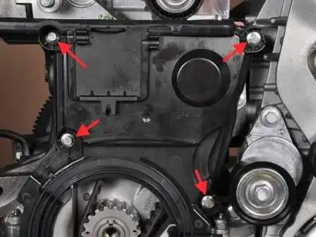
Using an 8 mm socket, we undo the four bolts securing the lower timing cover.
We remove the cover.
We set the crankshaft and camshafts to the top dead centre position of the first cylinder. To do this, we unscrew all the spark plugs.
We screw the auxiliary drive pulley bolt back into place, fitting a set of suitable washers.
To determine the position of the camshafts, it is necessary to withdraw the plugs from the openings in the left-hand end of the cylinder head.
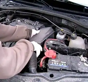
We remove the air intake with the resonator.
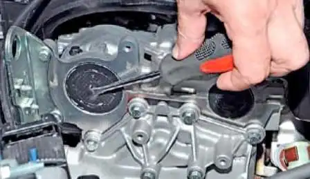
In the centre of the plug, we pierce an opening with a screwdriver.
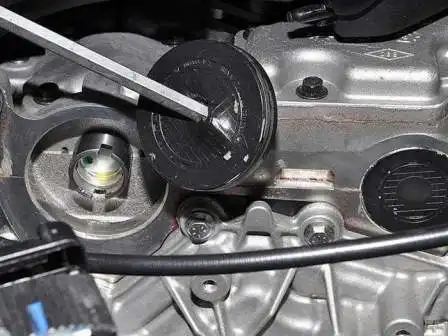
We withdraw the plug from the opening in the cylinder block. We also withdraw the other plug.
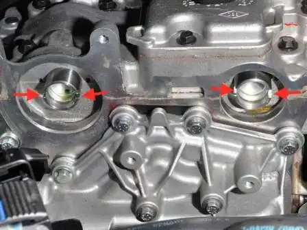
We turn the crankshaft clockwise; the slots on the ends of the camshafts must take up a horizontal position and be offset downwards relative to the camshaft axes.
To lock the camshafts in this position, a tool can be made from a metal plate five millimetres thick.
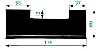
The dimensions of the tool are shown in the figure.
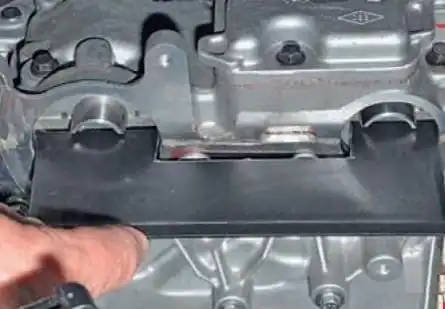
We fit the tool into the shaft slots.
We check that the crankshaft is at the TDC position of the pistons of cylinders 1 and 4. To do this:
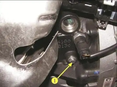
We undo the plug with an E14 socket.
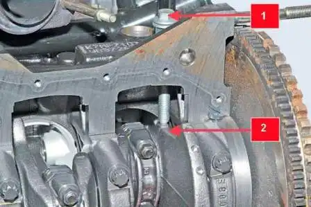
We insert the setting pin into the opening (shown with the sump removed).
When the crankshaft is at the TDC position of the pistons of cylinders 1 and 4, setting pin 1 should screw into the opening to the end of the thread and rest against the machined flat 2 on the crankshaft web.
After this, the crankshaft cannot be turned.
If, when screwing in the setting pin, it rests but the end of the adjusting nut on the pin does not touch the end of the boss of the opening in the cylinder block (a gap remains between the nut and the boss), the crankshaft must be turned slightly (after withdrawing the tool from the camshaft slots) anticlockwise.
Then the setting pin must be screwed into the cylinder block opening as far as it will go (until the ends of the pin nut and the boss of the opening in the block touch) and the crankshaft turned clockwise until the flat on the shaft web rests against the pin.
We fit the camshaft locking tool, if it was removed.
An M10 bolt can be used as the setting pin.
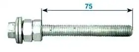
We screw two adjusting nuts onto the bolt and lock them so that the length of the threaded part of the bolt is 75 mm.
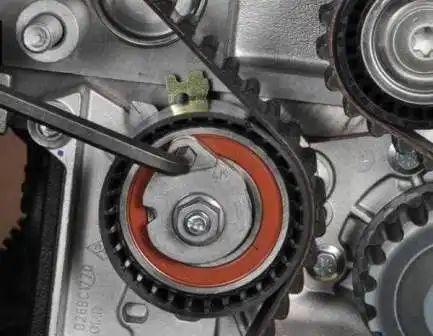
We turn the roller anticlockwise, reducing the timing drive tension.
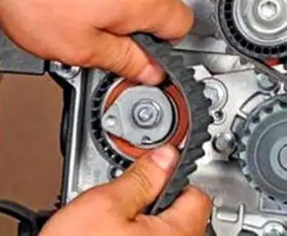
We remove the belt from the tensioner roller.
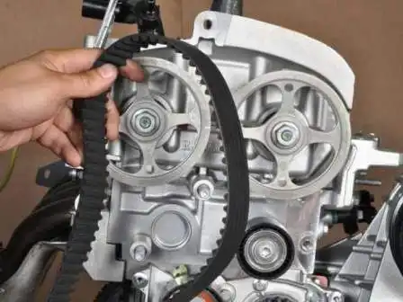
We remove the belt from the coolant pump, crankshaft and camshaft pulleys.
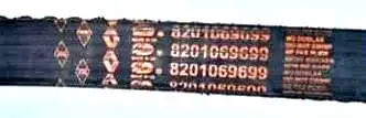
Marking of the belt (number of teeth 131, width 25.4 mm).
When replacing the belt, it is advisable to replace the tensioner and support rollers; to do this, we undo the tensioner roller securing nut.
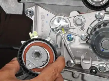
We remove the tensioner roller from the stud of the coolant pump housing.
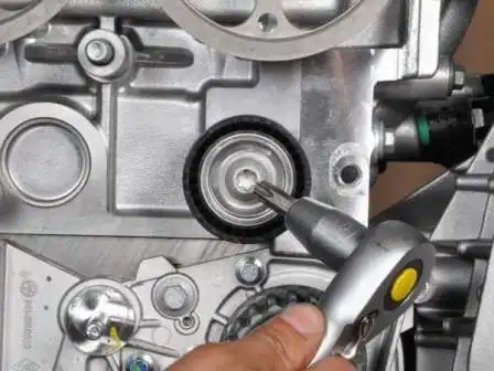
Using a TORX T50 key, we undo the screw securing the support roller.

We remove the support roller and its bush.
Installing the timing belt
We orient the belt so that the arrows on the belt coincide with the direction of belt travel clockwise.
We fit the belt onto the timing pulleys of the crankshaft, the coolant pump and the camshaft pulleys.
Then we simultaneously fit the belt onto the tensioner roller and fit the roller onto the stud of the coolant pump housing.
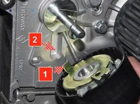
When fitting the tensioner roller, we insert the bent end 1 of the roller bracket into the recess 2 of the coolant pump housing.
We adjust the belt tension as described above.
We unscrew the locking pin from the opening in the cylinder block and remove the camshaft locking tool.
We turn the crankshaft two revolutions clockwise until the slots on the camshafts take up the position corresponding to top dead centre of piston 1.
We screw the plug into the cylinder block opening.
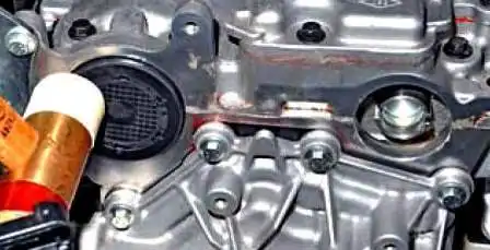
With light blows from a mallet with a plastic head, we press the new plugs into the openings of the cylinder head.
We reassemble the parts in the reverse order.
The bolt securing the auxiliary drive pulley is replaced with a new one and tightened to a torque of 40 Nm, then turned a further 110°.
The bolt securing the bracket of the tensioner roller of the auxiliary drive belt is tightened to a torque of 21 Nm.
The bolt securing the support roller of the timing belt is tightened to a torque of 50 Nm.
The nut securing the tensioner roller of the timing belt is tightened to a torque of 28 Nm.
The M8 bolt securing the upper timing cover is tightened to a torque of 22 Nm.
The M10 bolt securing the upper timing cover is tightened to a torque of 44 Nm.
The bolt securing the lower timing cover is tightened to a torque of 8 Nm.
Checking and replacing the timing belt on the F4R 2.0 l engine
We carry out the preparatory operations as described at the beginning of the article.
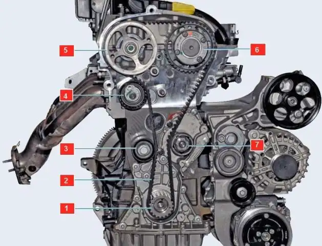
The belt installation diagram is shown in figure 1.
We remove the right-hand mount, as described above.
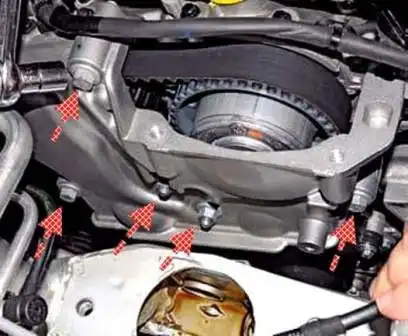
Using a 13 mm socket, we undo the three bolts and two nuts securing the upper timing cover.
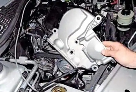
We remove the cover.
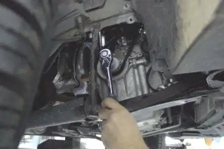
Using an 18 mm socket, we turn the crankshaft clockwise and assess the condition of the belt.
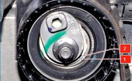
With normal belt tension, the movable indicator 1 should coincide with the recess of the fixed indicator.
If the movable indicator is offset, we tighten the belt.
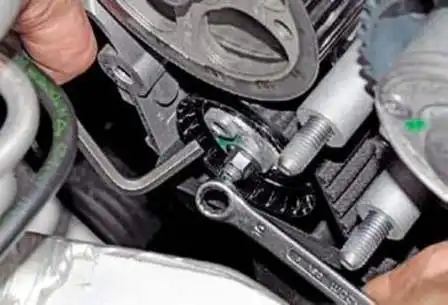
Using a 10 mm ring spanner, we loosen the nut securing the tensioner roller and, using a 6 mm hex key, turn the roller clockwise, tensioning the belt until the marks coincide.
We tighten the nut in this position.
To replace the timing belt, we remove the auxiliary drive belt (article — Checking and replacing the auxiliary drive belt).
After this, we undo the auxiliary drive pulley, as described above.
If the pulley securing bolt cannot be undone, the shaft must be locked.
To do this:
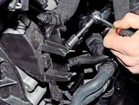
Using a 13 mm socket, we undo the bolt securing the plastic wiring harness holder to the clutch housing.
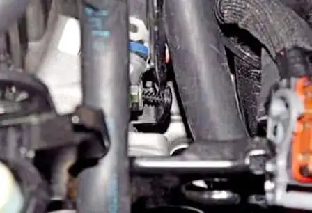
We withdraw the bolt.
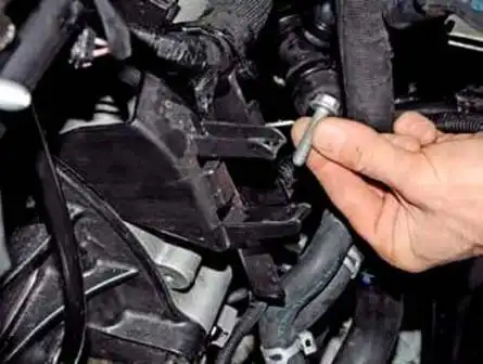
Using a flat screwdriver, we prise up the push rivet securing the wiring harness holder and withdraw it from the opening in the thermostat housing.
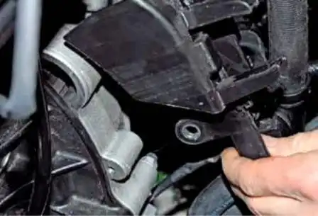
We move the harness holder with the wiring harnesses away from the clutch housing.
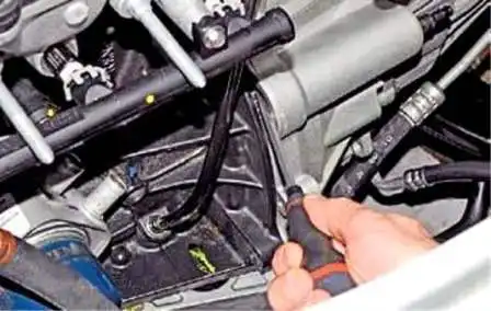
Through the window in the clutch housing, we insert a screwdriver between the teeth of the flywheel ring gear.
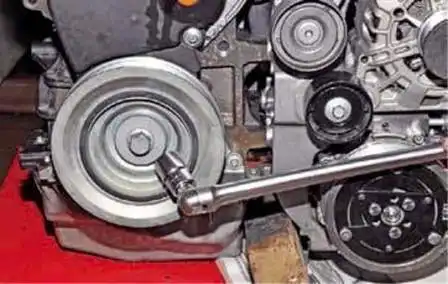
Using an 18 mm socket, we undo the bolt securing the auxiliary drive pulley.
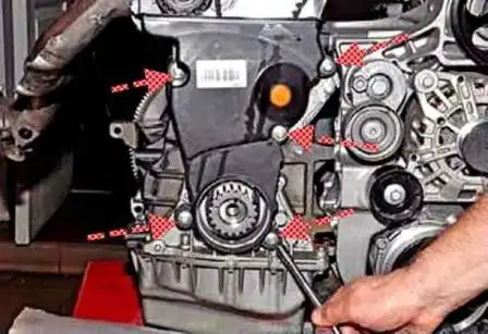
Using an 8 mm socket, we undo the five bolts securing the lower timing cover.
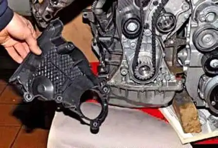
We remove the cover.
To turn the crankshaft, we screw the auxiliary drive pulley bolt back into place, fitting a bush or washers between the bolt and the shaft end.
We unscrew all the spark plugs to make turning the crankshaft easier.
We withdraw the camshaft plugs, as described above.
We turn the crankshaft clockwise until the slots take up a horizontal position and are directed downwards relative to the camshaft axes.
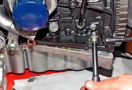
Using an E14 socket, we unscrew the plug from the opening in the cylinder block.
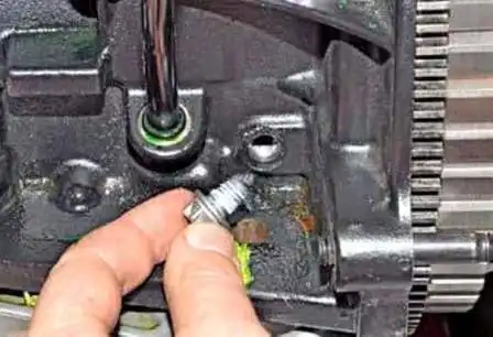
We withdraw the plug.
We insert the setting pin into the cylinder block opening.
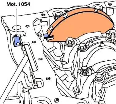
When the crankshaft is at the TDC position of the pistons of cylinders 1 and 4, the pin must enter the rectangular slot on the crankshaft web and lock the shaft.
When attempting to turn the crankshaft in either direction, it must not move.
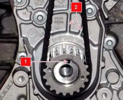
In the correct position, slot 1 on its nose must be located between two ribs 2 of the cylinder block cover.
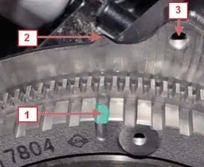
When assembling the engine, it is convenient to check the position of the crankshaft at TDC of cylinders 1 and 4 by the coincidence of recess 1 of the target disc (for the crankshaft position sensor) on the flywheel with boss 2 on the cylinder block (3 — opening for the bolt of the upper front gearbox mounting).
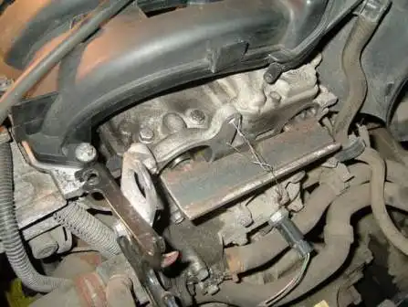
We fit the locking tool into the slots of the camshafts.
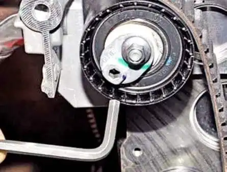
Using a 6 mm hex key, we turn the roller anticlockwise, releasing the belt tension.
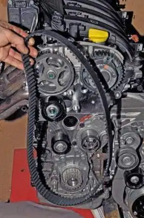
We remove the timing belt.
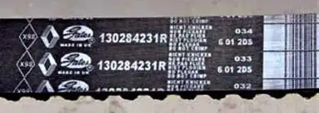
Marking of the timing belt (number of teeth — 126, width 25.4 mm).
We replace the tensioner and support rollers; to do this:
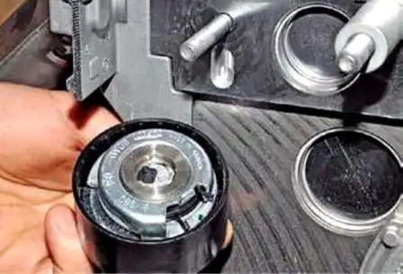
After undoing the securing nut, we remove the tensioner roller from the stud of the cylinder head.
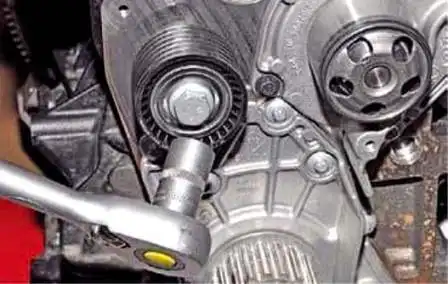
Using a 16 mm socket, we undo the bolt securing the support roller to the cylinder block.
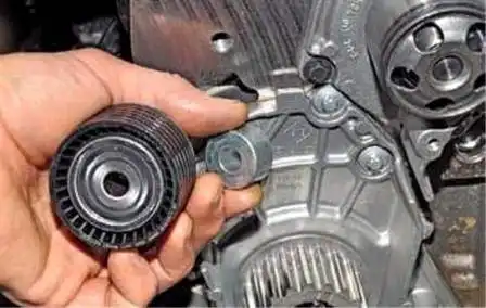
We remove the support roller and its setting bush.
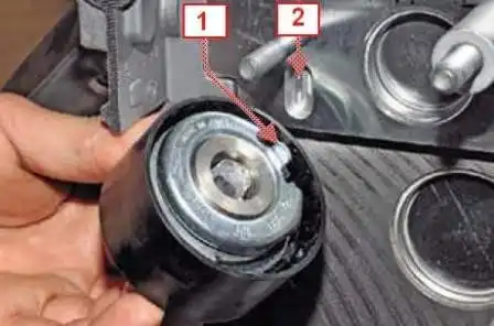
When fitting the tensioner roller, we insert the bent end 1 of its bracket into the recess 2 of the cylinder head and start the roller securing nut.
The arrows on the belt, when fitting the belt, must coincide with the direction of belt travel (clockwise).
We route the front run of the belt under the coolant pump pulley, and the rear run of the belt under the tensioner and support rollers.
We adjust the timing belt tension as described above.
We withdraw the setting pin from the cylinder block opening and remove the camshaft locking tool.
We turn the crankshaft two revolutions clockwise until the slots on the ends of the camshafts take up the required position.
We check the valve timing and belt tension and, if necessary, repeat the adjustments.
We refit the threaded plug and press in the new camshaft plugs, as shown for the 1.6 l engine.
We reassemble the parts in the reverse order.
The bolt securing the auxiliary drive pulley is replaced with a new one and tightened to a torque of 40 Nm, then turned a further 110°.
The bolt securing the bracket of the tensioner roller of the auxiliary drive belt is tightened to a torque of 21 Nm.
The bolt securing the support roller of the timing belt is tightened to a torque of 50 Nm.
The nut securing the tensioner roller of the timing belt is tightened to a torque of 28 Nm.
The M8 bolt securing the upper timing cover is tightened to a torque of 22 Nm.
The M10 bolt securing the upper timing cover is tightened to a torque of 44 Nm.
The bolt securing the lower timing cover is tightened to a torque of 8 Nm.


