The power supply system includes elements of the following subsystems:
- - fuel supply, including a fuel tank, an electric fuel pump with a filter, a fuel pressure regulator, pipelines and a fuel rail with injectors;
- - air supply system, consisting of an air supply hose, an air filter, a throttle assembly, an idle speed controller;
- - a fuel vapor recovery system, which includes an adsorber, a control valve and connecting pipelines.
The functional purpose of the supply subsystem is to ensure the supply of the required amount of fuel to the engine in all operating modes.
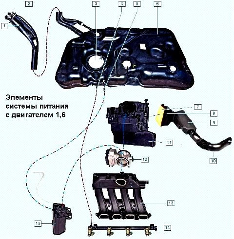
The engines are equipped with an electronic engine management system with multiport fuel injection.
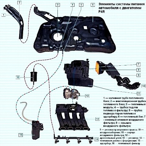
In the multiport injection system, the functions of mixture formation and dosing of the air-fuel mixture supply to the engine cylinders are separated.
Air is supplied by an air supply subsystem consisting of a throttle assembly, and the amount of fuel required at each moment of engine operation is injected into the intake pipe by nozzles.
This control method makes it possible to ensure the optimal composition of the combustible mixture at each particular moment of engine operation, which allows you to get maximum power with the lowest possible fuel consumption and low exhaust gas toxicity.
The fuel injection system (as well as the ignition system) is controlled by an electronic unit that continuously monitors the engine load, the vehicle speed, the thermal state of the engine, and the optimal combustion process in the engine cylinders using appropriate sensors.
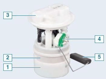
The fuel pump module includes an electric pump, a fuel fine filter, a fuel pressure regulator and a fuel gauge sensor.
The fuel pump module delivers fuel and is installed in the fuel tank, which reduces the possibility of vapor lock because the fuel is supplied under pressure, not under vacuum.
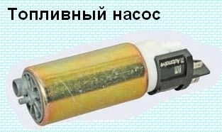
Submersible fuel pump, electrically driven, rotary type.
The pump of a non-separable design cannot be repaired; if it fails, it must be replaced.
The fuel gauge sensor is attached to the fuel module body.
The fuel gauge sensor is a variable resistor whose resistance depends on the movement of the float.
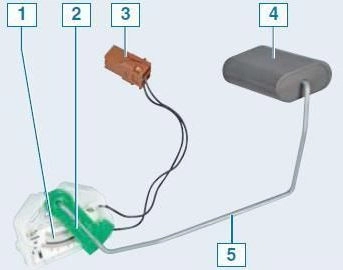
The sensor controls the operation of the fuel level indicator and the minimum fuel level indicator located in the instrument cluster.
The fuel pump is located inside the fuel module housing.
The pump is electric, vortex type.
It turns on at the command of the electronic engine control unit when the ignition is turned on and supplies fuel to the line at a pressure (about 6.0 bar) exceeding the operating pressure in the fuel rail.
Fuel passing through the pump lubricates and cools the pump during its operation.
Therefore, it is forbidden to turn on the pump even for a short time if there is no fuel in the tank.
From the pump, fuel is supplied through a corrugated plastic tube to the filter and fuel pressure regulator, which are part of the fuel module.
The fuel filter (not replaceable) is designed to clean the fuel from mechanical impurities.
If the filter is clogged, the fuel module must be replaced.
The fuel pressure regulator is a valve that opens when the specified fuel pressure in the line is exceeded and bleeds some of the fuel into the tank.
The fuel pressure in the line with the ignition on and the engine off should be about 3.2 bar.
If the pressure regulator fails, the fuel module must be replaced.
From the filter housing, fuel is supplied through a corrugated plastic tube to the module cover.
The tip of the fuel pipe passing under the bottom of the car is connected to the outlet fitting of the fuel module cover.
The other end of the fuel pipe in the engine compartment is connected to the fuel rail fitting (vehicle with a 1.6 engine) or fuel filter fitting (vehicle with a 2.0 engine).
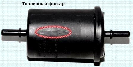
The fuel filter is fixed in the engine compartment on the right side.
The other fuel filter fitting is connected by a tube to the fuel rail fitting.
In accordance with the vehicle maintenance regulations, the fuel filter located in the engine compartment must be replaced every 120 thousand kilometers.
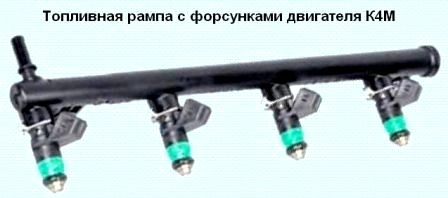
The fuel rail is a tube made of high-strength heat-resistant plastic, on which nozzles are installed.
The rail is attached to the intake manifold with two bolts.

The fuel rails and injectors of the 1.6 and 2.0 engines are different.
Fuel under pressure is supplied to the cavity of the rail, and from there through the nozzles - to the channels of the intake pipeline.
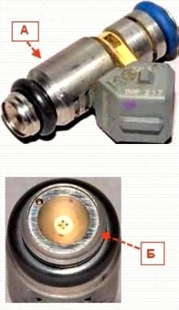
The injector is a solenoid valve that injects fuel into the intake manifold channel when voltage is applied to it and locks under the action of a return spring when de-energized.
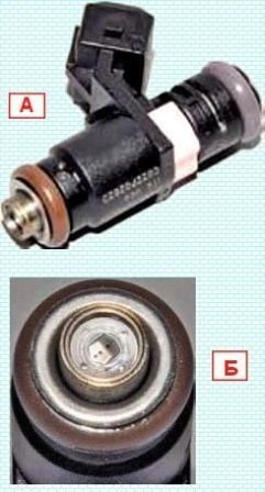
At the nozzle outlet, there is a sprayer with four holes through which fuel is injected into the channels of the inlet pipeline.
Controls the operation of the ECU injectors.
The injectors are sealed in the rail and intake manifold with rubber rings and fixed to the rail with metal clips.
If the winding is broken or shorted, the nozzle should be replaced.
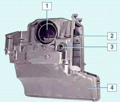
Air is supplied to the channels of the engine cylinder head through the air intake, resonator, air filter, throttle assembly, reservoir and intake pipeline.
The resonator absorbs air pressure waves and reduces intake noise.
The air filter housing is made of high-strength heat-resistant plastic and is mounted on the rear side of the engine.
A replaceable filter element (paper) is adjacent to the air supply hole in the housing, which is closed by a cover.
A neck is made in the filter housing, which is connected to the nozzle of the throttle assembly.
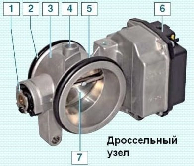
The throttle assembly is the simplest control device and serves to change the amount of main air supplied to the engine intake system.
It is installed on the inlet flange of the intake manifold.
A branch pipe of the air intake chamber body is put on the inlet pipe of the throttle assembly.
The throttle assembly includes a throttle control stepper motor.
There is no mechanical connection between the throttle assembly and the throttle control pedal.
The so-called "electronic throttle pedal" transmits information about the degree of depression on the pedal to the electronic engine control unit, which, in turn, taking into account the vehicle speed, gear engaged, engine load and engine speed, opens the throttle valve to the required angle .
On the K4M engine, the damper is driven by a cable.
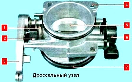
At one end of the throttle axis, lever 3 is installed, to which an intermediate drive rod is attached, at the other end is a damper position sensor 6.
On the F4R motor, the throttle valve is driven by a stepper motor.
There is no mechanical connection between the throttle assembly and the throttle control pedal.
The so-called "electronic" throttle pedal transmits information about the degree of depression on the pedal to the electronic engine control unit, which, in turn, taking into account the vehicle speed, gear engaged, engine load and engine speed, opens the throttle to the required angle.
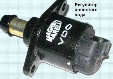
The K4M engine idle speed controller maintains the set engine idle speed with the throttle valve fully closed during its start-up, warm-up and when the load changes when auxiliary equipment is turned on.
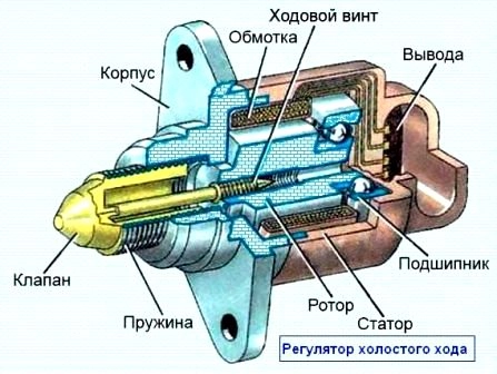
The regulator changes the amount of additional air supplied to the intake system in addition to the throttle, and is an electromechanical valve attached with two screws to the flange of the air filter housing.
The regulator valve seat and channels made in the filter flange form an additional air supply system, bypassing the throttle valve.
The engine control unit, having processed the signals from the sensors, determines Determines the need to open the valve (figure) of the regulator and transmits impulses to the stator winding of the regulator.
With each control pulse, the rotor rotates through a certain angle, moving the valve relative to the seat with the lead screw.
Additional air enters the intake pipe.
Determining the vacuum in the engine intake pipe, the control unit seeks to maintain it at a given level by periodically opening and closing the idle air control valve.
This makes it possible to supply a constant amount of additional air to maintain a constant idle speed.
By changing the opening and closing of the regulator valve, the control unit compensates for a significant increase or decrease in the amount of air supplied, caused by its suction through a leaky intake system or, conversely, by a clogged air filter.
The inclusion of additional units causes an increase in the load on the engine, accompanied by a decrease in the idling speed and a change in the vacuum in the intake pipe, which is also compensated by the control unit using the regulator.
The throttle assembly of the F4R engine does not have an idle speed control.
The electronic control unit maintains the required speed of the crankshaft in idle mode by changing the throttle opening angle using a stepper motor.
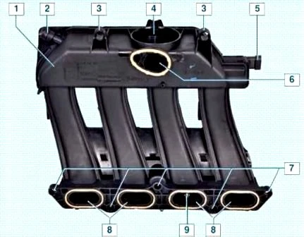
After passing the throttle assembly, the air enters the receiver, made of high-strength heat-resistant plastic.
The reservoir is mounted on top of the cylinder head cover.
From the common cavity of the receiver, air passes through four channels to the channels of the inlet pipeline.
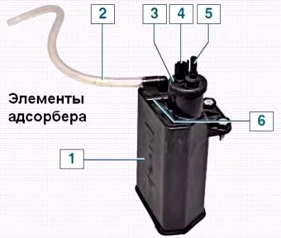
The fuel vapor recovery system used in the power system includes an adsorber, an adsorber purge solenoid valve and connecting pipes.
From the fuel tank, gasoline vapors enter the adsorber (installed behind the front bumper, in front of the wheel arch of the right wheel) through a plastic tube passing under the bottom of the car, where they are absorbed by a sorbent (activated carbon).
At the top of the adsorber there is an adsorber purge solenoid valve.
The valve is connected by a plastic tube to the throttle space of the throttle assembly.
When the engine is stopped, the purge solenoid valve is closed, and in this case the adsorber does not communicate with the throttle assembly.
The ECU, by controlling the solenoid valve, purges the canister after the engine has been running for a predetermined period of time from the moment of switching to the closed-loop fuel control mode (the control oxygen sensor must be warmed up to the required temperature).
The valve communicates the cavity of the adsorber with the throttle assembly, and the sorbent is purged: gasoline vapors mix with air and enter through the throttle assembly and receiver into the intake pipeline and then into the engine cylinders.
The greater the air consumption of the engine, the longer the duration of the control pulses of the computer and the more intense the purge.


