


The vehicle may be equipped either with a heating and ventilation system, or with a heating, ventilation and air conditioning system, which serve to create the most comfortable conditions for the driver and passengers regardless of the weather conditions
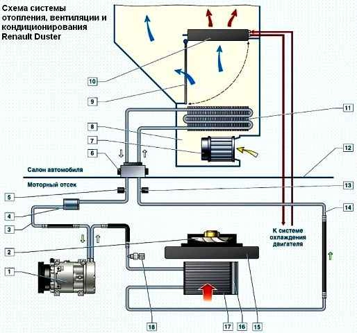
The heating and ventilation system includes: the heater, the heater blower, the air ducts and the deflectors.
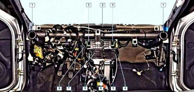
Through the air ducts, the air from the heater is supplied to the demist grilles of the windscreen and side windows, to the central and side deflectors of the instrument panel, as well as to the ventilation openings in the heater casing for supplying air to the feet of the driver and passengers.
The system is controlled by turning the knobs located on the heater, ventilation and air conditioning control unit.
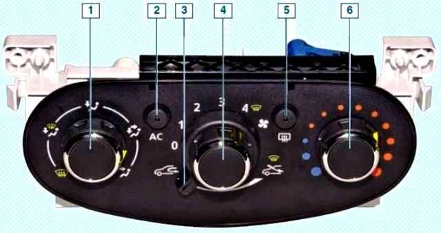
The control unit is installed on the instrument panel console.
The heater is installed under the instrument panel in the centre, the air ducts are secured under the crossmember of the instrument panel.
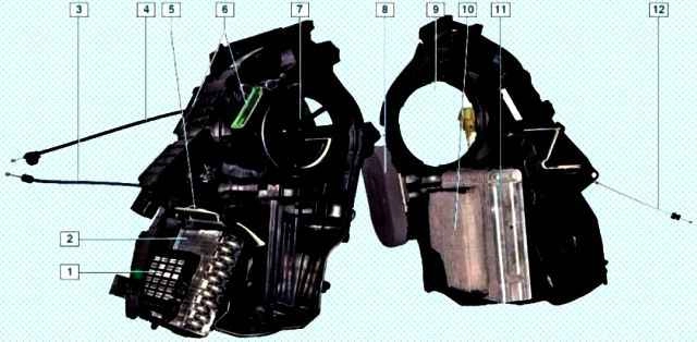
In the heater housing is installed the heater blower.
The additional blower resistor, the additional cabin electric heater (on some vehicles), the air conditioning evaporator (on the vehicle with air conditioning), the distribution flaps, which direct the air flows to certain zones, and the heater radiator, connected by hoses to the engine cooling system.
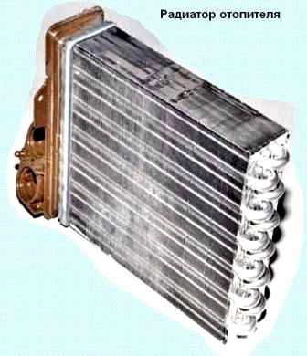
Coolant circulates constantly through the radiator.
Depending on the position of the flap, linked to the temperature regulator, the outside air may pass through the heater radiator or bypass it.
In the intermediate positions of the flap, part of the air passes through the radiator, and the rest bypasses the radiator.
In the extreme positions of the flap, all the air passes through the radiator or bypasses it.
When the vehicle is moving, the air enters the heater through the openings located in the left and right facings of the windscreen.
To increase the air supply to the cabin while the vehicle is moving, as well as when stationary, the heater blower serves.
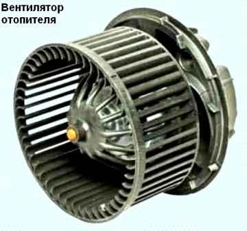
The intensity of the air supply is determined by the rotation speed of the blower.
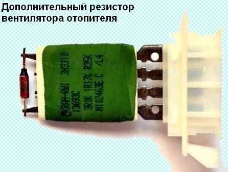
The electric motor of the blower, depending on the connection of the additional resistor, can rotate at four different speeds.
The control of the air flows in the cabin is carried out by the air flow distribution regulator, which is linked by rods to the flaps.
Turning the flaps, the regulator directs the air flows through the air ducts to the central and side deflectors, to the lower ventilation openings in the heater casing, as well as to the demist grilles of the windows, located in the instrument panel.
From the cabin, the air exits through the slots in the luggage compartment trim and then to the outside, through the valves installed behind the sides of the rear bumper.
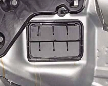
To accelerate the warming up of the cabin and to prevent the entry of outside air into the cabin (when the vehicle is moving along smoky or dusty sections of road), the air recirculation system serves.
When the air recirculation mode activation knob is turned, the recirculation system flap closes the access of outside air into the vehicle cabin, and the air in the vehicle cabin begins to circulate in a closed circuit without exchange with the outside air.
On some vehicles, an additional cabin electric heater is installed in the heater housing.
If the temperature regulator knob is turned to the red zone and the engine is not warmed up to operating temperature, the engine control unit switches on the additional electric heater.
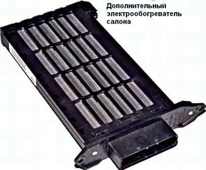
To switch on the electric heater, two relays installed under the instrument panel serve.
Some vehicles are equipped with an air conditioning system.
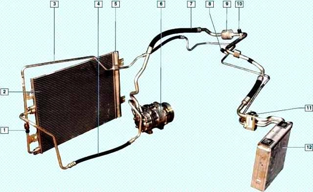
The air conditioning system is intended to reduce the temperature and humidity of the air in the cabin.
The air conditioning is switched on by pressing the button of the air conditioning switch, located in the heater, ventilation and air conditioning control unit, and the heater blower must be switched on.
When the air conditioning is switched on, the indicator lamp located in the button of the air conditioning switch lights up.
The air conditioning compressor is installed on the engine bracket at the front, under the alternator.
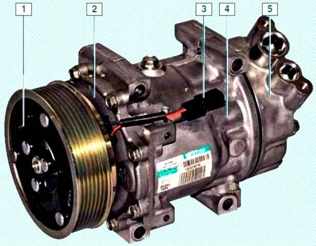
The compressor compresses the refrigerant arriving to it from the evaporator, being in the vapour state under low pressure of 0.5—2.0 bar.
At the outlet of the compressor, the pressure of the refrigerant vapours rises, and the temperature reaches 80—100 °C.
The drive of the air conditioning compressor is carried out by a poly-V belt from the drive pulley of the auxiliary units.
A friction electromagnetic clutch is built into the compressor pulley, which connects-disconnects the compressor shaft with the pulley according to the signals of the engine control unit.
From the compressor, the refrigerant vapours enter the condenser, located in front of the engine cooling system radiator.
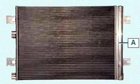
When the plates of the condenser are blown by the air flow created during the movement of the vehicle, as well as with the help of the cooling system fan, the refrigerant under high pressure (15.0-20.0 bar) changes from the gaseous state to the liquid state.
A receiver-drier is built into the right part of the condenser.
The receiver-drier is also provided with a filter for cleaning the refrigerant from impurities.
From the condenser, the refrigerant enters the expansion valve, which is a throttle valve, at the outlet of which the pressure and temperature of the refrigerant sharply decrease (to 1.0 bar and to -7 °C).
As a result, the refrigerant enters the evaporator, located in the heater housing.
The air flow passing in the heater housing through the evaporator under the action of the heater blower causes the evaporation of the refrigerant.
At the same time, the air, giving up heat to the refrigerant in the evaporator, becomes colder.
From the evaporator, the refrigerant is again drawn in by the compressor, and the working cycle is repeated.
On the high-pressure and low-pressure pipelines, valves are installed for charging and discharging the refrigerant from the air conditioning system.
On the pipeline between the compressor and the condenser, a refrigerant pressure sensor is installed.
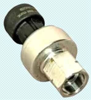
The sensor gives a signal to the engine control unit, which controls the engine cooling system fan depending on the value of the refrigerant pressure and the speed of the vehicle.
Moreover, according to the signals of the pressure sensor, the engine control unit switches off the air conditioning compressor when the refrigerant pressure in the system falls to 2.0 bar and when the pressure rises to 27.0 bar.
In the union of the pipeline under the pressure sensor, a shut-off valve is installed, which closes when the sensor is unscrewed.
Therefore, when replacing the pressure sensor, no refrigerant leakage from the air conditioning system occurs.
The refrigerant in the air conditioning system is under high pressure.
During work involving the depressurisation of the air conditioning system, the ingress of refrigerant into the eyes, on the skin and into the respiratory tract should be avoided.
Any work with the refrigerant must be carried out only in a ventilated room.
When charging the air conditioning system, only the materials recommended by the manufacturer should be used.
It is prohibited to carry out welding or soldering work on the components of the air conditioning system.
Maintenance and repair work on the air conditioning system should be carried out at specialised service centres.
To search for leaks in the system, special equipment is used, and a special contrast substance will need to be introduced into the system.
After removing the refrigerant from the system, it is imperative to pump out the air in order to remove the remnants of moisture.
Before charging, special oil must be added to the system.


