We remove the cylinder head to replace the gasket under the block head, as well as for repair.
Disconnect the negative battery terminal
Draining the coolant
We remove the drive belt of mounted units (article - Replacing the drive belt of mounted units Cummins ISF3.8)
Removing the turbocharger
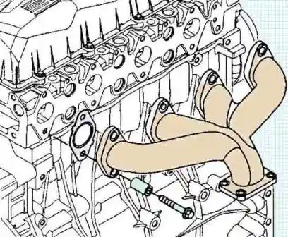
Remove the exhaust manifold (for complete disassembly of the cylinder head, you can not remove it when replacing the gasket)
Remove the thermostat housing and take out the thermostat
Remove the coolant bypass pipe
Remove high pressure fuel pipes
Unscrew and remove the ramp
Remove the intake manifold
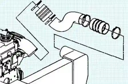
To do this, we loosen the clamps of the air ducts of the intercooler of the charge air, remove the air duct.
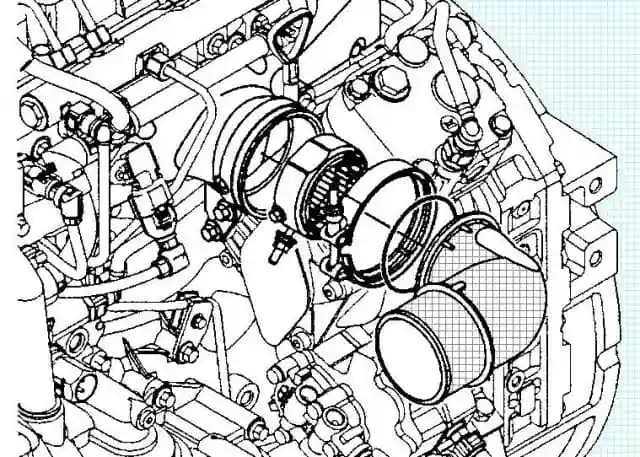
We unscrew the mounting bolts, remove the air elbow, the top gasket, the air heater at the inlet of the starting aid and the bottom gasket.
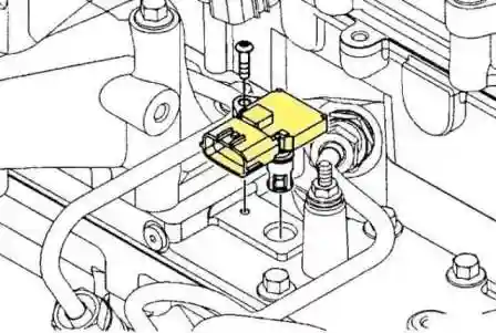
Remove the pressure sensor in the intake manifold with the temperature sensor assembly:
- - disconnect the intake manifold pressure sensor connector;
- - unscrew the screw;
- - remove the sensor straight up, trying not to damage the O-ring.
We unscrew all the bolts securing the intake manifold to the cylinder head and remove the intake manifold.
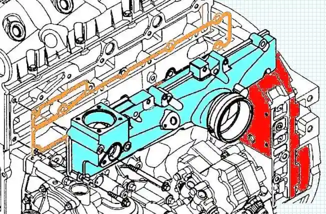
Removing the gasket
We tape the channels in the cylinder head so that debris does not get in.
Remove the fuel outlet pipes.
Disconnecting the air compressor cooling pipes
Remove the cylinder head cover:
- - disconnect the engine wiring:
- - loosen the screws securing the cylinder head cover (the screws are not removable and are part of the cover).
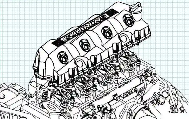
Carefully lift and remove the lid
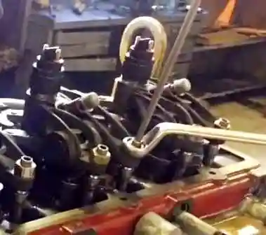
Remove the valve levers (rocker arms) for this:
- - loosen the locknut;
- - unscrew the adjusting nut;
- - unscrew the rocker bolts;
- - remove rocker arms and valve bridges. Bridges and rocker arms must be installed in their places, so we mark them and lay them out on the table in the right order.
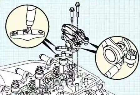
Remove push rods.
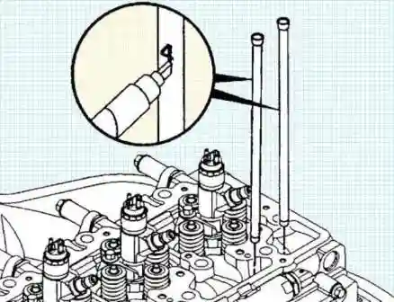
We put marks on the rods for their location. The bars must be installed in their places.
Remove the nozzles.
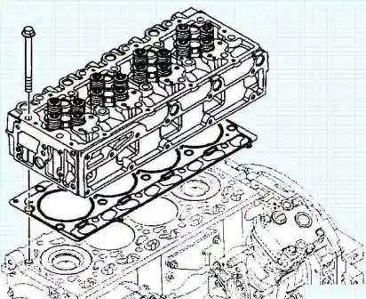
After that, evenly in several passes, we unscrew the bolts and remove the cylinder head.
Disassembly, inspection, cleaning and repair of the cylinder head will be discussed in a separate article.
Installing the cylinder head
Install a new cylinder head gasket.
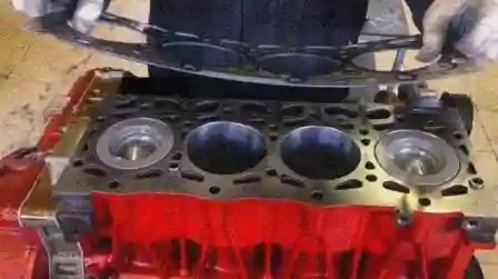
Depending on the protrusion of the piston, one of three sizes of cylinder head gasket can be installed after grinding the cylinder head or cylinder block.
If the piston protrusion exceeds 0.5 mm, the cylinder block must be replaced.

Cylinder head gasket thickness:
- - nominal spacer 1.25 mm
- - repair No. 1 -1.50 mm
- - repair - №2 - 1.75 mm
Install the cylinder head.
- a) Carefully lower the cylinder head onto the cylinder block locating pins.
Note: The cylinder head weighs over 23 kg.
- b) Lubricate the threads and under the bolt heads with engine oil.
- c) Install the bolts and tighten them by hand.
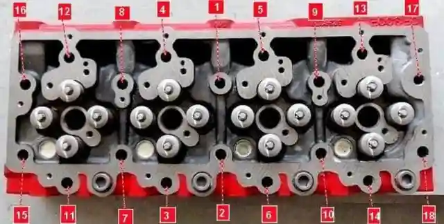
- d) Tighten the cylinder head bolts in the sequence shown in the figure.
Tightening torque:
- - first stage 70Nm
- - Step 2 loosen 180°
- - Stage 3 60 nm
- - stage 4 60 Nm,
- - rotate 90˚
- - turn 90°
Install the nozzles.
Install the push rods.
Note: the rods must be installed in the places where they were removed from.
a) Install the rods in the plunger recess.
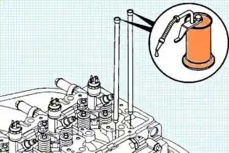
b) Lubricate the end of the rod with engine oil
Install the rocker arm assembly.
Note: all parts of the rocker arms must be installed in the places where they were removed.
a) Fully tighten the adjusting screws, then tighten the locknut.
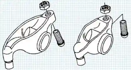
- b) Lubricate the rocker shafts with engine oil
- c) Install the axles in the rocker arms.
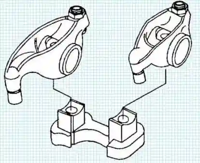
- d) Install the rockers on the support.
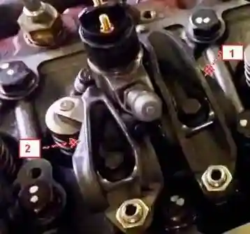
Note: Do not confuse the intake and exhaust rocker arms.
- e) Install the valve bridges in the places where they were removed.
- e) Install the rocker arms with supports in the place where they were removed.
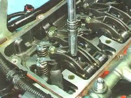
g) Tighten the support bolts.
Tightening torque 36 Nm
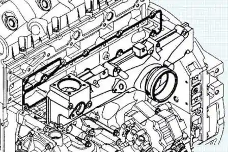
Install the intake manifold.
a) Install the intake manifold and tighten the bolts.
Apply threadlocker (#3824041) to the bolts before installation.
If the intake manifold was installed through a gasket, Change the gasket to a new one.
If the intake manifold was fitted with RTV sealant, remove the old sealant and apply new sealant (#3164070).
Tightening torque 24 Nm
Install the cylinder head cover.
- a) Install the cylinder head cover.
- b) Tighten the screws.
Tightening torque 9 Nm
Install the fuel rail.
Install the fuel return pipes.
Install the high pressure fuel lines.
Install the coolant bypass pipe.
Install the thermostat housing.
Install the exhaust manifold.
- a) Apply a high temperature anti-seize compound to the exhaust manifold mounting bolts.
- b) Install the exhaust manifold, new gaskets, spacers and retaining plates.
- c) Tighten the exhaust manifold mounting bolts in the sequence shown in the figure.
Tightening torque 53 Nm
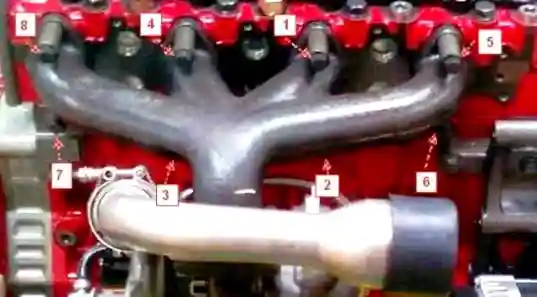
Install the turbocharger.
Install the accessory drive belt.
Connect the air compressor cooling pipes to the cylinder head.
Connect the wires to the battery.
Refill coolant.
Start the engine and check for leaks.


