The diesel power system consists of a Common RAIL battery injection system, low and high pressure fuel lines, intake and exhaust manifolds; turbocharger; fine and coarse fuel filters, air cleaner, fuel tank, charge air cooler
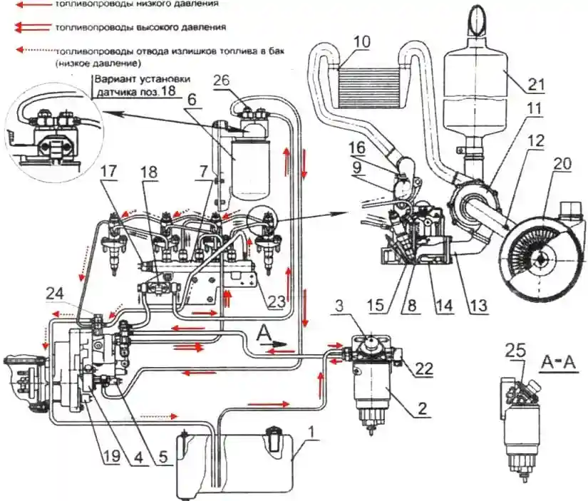
Scheme of the power supply system: 1 - fuel tank; 2 - coarse fuel filter; 3 - manual fuel priming pump; 4 - high pressure fuel pump; 5 - electromagnetic pressure regulator, 6 - fuel fine filter; 7 - high pressure fuel accumulator; 8 - nozzle; 9 - intake manifold; 10 - charge air cooler 11 - turbocharger; 12 - air filter clogging sensor; 13 - exhaust manifold; 14 - cylinder head; 15 - glow plug; 16 - charge air temperature and pressure sensor; 17 - fuel high pressure sensor; 18 - fuel temperature and pressure sensor; 19 - camshaft speed sensor; 20 - air cleaner; 21 - silencer; 22 - fuel heater; 23 - pressure limiting valve; 24 - a bolt of a rotary square; 25 - plug for air release; 26 - cork
The Common RAIL battery injection system consists of a fuel pump, an injector, a high-pressure fuel accumulator, speed sensors (crankshaft and camshaft), sensors for the state of the working environment (fuel and air pressure and temperature), electromagnetic actuators (regulator fuel pressure, injector solenoid valves), electronic unit, control and communication control circuits, control and diagnostic panels.
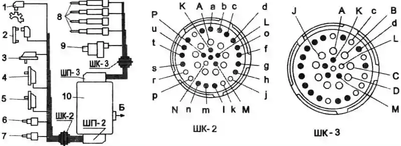
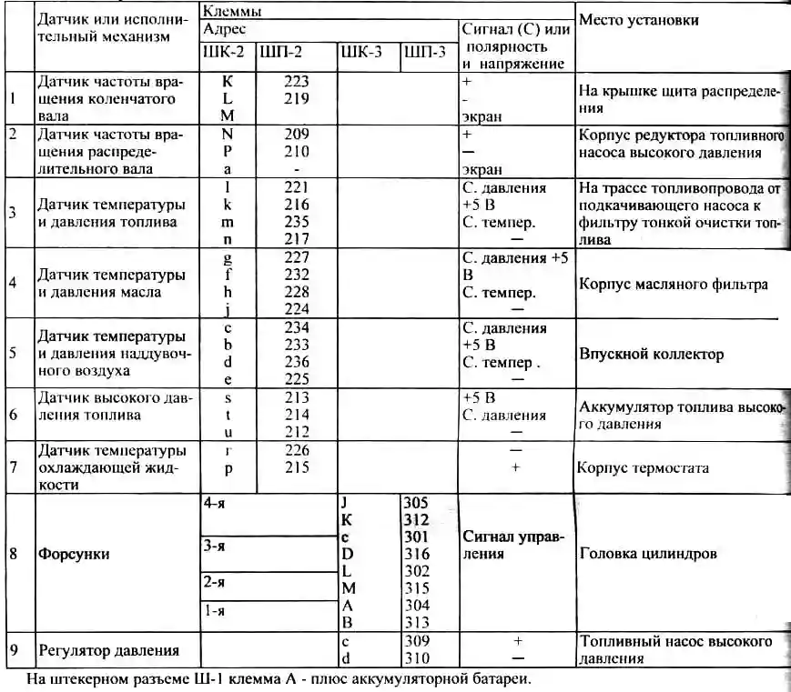
COMMON RAIL monitoring and control circuit diagram: 1 - crankshaft speed sensor; 2 - camshaft speed sensor; 3 - fuel temperature and pressure sensor; 4 - oil temperature and pressure sensor; 5 - charge air temperature and pressure sensor; 6 - fuel high pressure sensor; 7 - coolant temperature sensor; 8 - nozzles; 9 - pressure regulator; 10 - electronic control unit; B - to the scheme of the onboard network of the bus
Scheme of control and control circuits of the COMMON RAIL power supply system is shown in Figure 2.
High pressure fuel pump (high pressure fuel pump, mod. СР3.3, fig. 3) is designed to create a reserve of fuel, maintain and regulate pressure in the fuel accumulator.
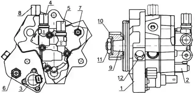
High pressure fuel pump SRZ.Z: 1 - high pressure fuel pump; 2 - fuel priming pump; 3 - electromagnetic pressure regulator; 4 - fuel supply fitting from the coarse fuel filter; 5 - fuel outlet fitting to the fine fuel filter; 6 - fuel supply fitting from the fine fuel filter; 7 - fuel outlet fitting to the fuel accumulator; 8 - fuel outlet to the tank; 9 - drive shaft; 10 - drive gear; 11 - nut; 12 - cork
A fuel priming pump 2, driven by a shaft 9, and an electromagnetic pressure regulator 3 are fixed on the injection pump housing.
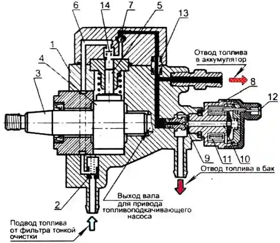
Scheme of injection pump: 1 - casing of injection pump; 2 - protective valve with a throttle hole; 3 - drive shaft; 4 - cam rotor; 5 - plunger; 6 - supply channel; 7 - exhaust valve; 8 - pressure control valve; 9 - ball; 10 - anchor; 11 - electromagnet; 12 - electromagnet terminals; 13 - seal; 14 - inlet valve
Three plungers 5 are located radially with an angle interval of 120° in the injection pump housing (Fig. 4.), and a cam rotor 4 is installed on the drive shaft 3 (the cams are located at 120° intervals around the circumference of the rotor).
The drive shaft of the high-pressure fuel pump with a cam rotor has a gear drive from a gearbox, the input the shaft of which, through the half-coupling of the drive, is in kinematic communication with the crankshaft of the diesel engine through the distribution gears.
Fuel that has passed through a coarse fuel filter with a moisture separator is supplied at a pressure of 0.8 ... 0.9 MPa by a fuel priming pump through a fine fuel filter to the inlet fitting of the injection pump.
Lubrication and cooling of high-pressure fuel pump parts is carried out by diesel fuel entering the high-pressure fuel pump.
Under the influence of the created boost pressure, the protective valve 2 opens access to the fuel through the supply channel 6 to the above-plunger spaces.
The incoming cam of the rotor moves the plunger upwards, while the inlet of the inlet channel is blocked and as the plunger further rises, the fuel is compressed in the space above the plunger.
When the increasing pressure reaches a level corresponding to that maintained in the high pressure accumulator, the outlet valve 7 opens.
Compressed fuel enters the high pressure circuit.
The plunger delivers fuel until it reaches TDC (delivery stroke). Then the pressure drops, the outlet valve closes.
The plunger starts moving down. For one revolution of the shaft, each (out of three) plunger makes one pumping stroke.
Since the high-pressure fuel pump is designed for a large flow rate, an excess of compressed fuel occurs at idle and at partial loads, which returns to the fuel tank through the pressure control valve 8 and the backflow line.
The pressure control valve sets the pressure in the high pressure accumulator depending on the engine load, engine speed and thermal state of the engine.
If the pressure in the accumulator is too high, the valve opens and part of the fuel from the accumulator
is discharged through the backflow line back to the fuel tank.
The pressure control valve is flanged to the injection pump housing.
Anchor 10 presses the valve ball 9 against the seat under the action of the valve spring so as to separate the high and low pressure circuits.
The switched on electromagnet 11 moves the armature, applying additional force to press the ball against the seat.
The entire anchor is washed with fuel, which lubricates the rubbing surfaces and removes excess heat.
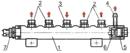
High pressure fuel accumulator (rail): 1 - high pressure fuel accumulator; 2 - outlet fittings; 3 - inlet fitting; 4 - backflow fitting; 5 - pressure limiting valve; 6 - shut-off cone of the valve core; 7 - fuel pressure sensor
The high-pressure fuel storage (Rail) is a volumetric storage of high-pressure fuel (fig. 5).
At the same time, the accumulator smooths out pressure fluctuations that occur due to the pulsating fuel supply from the injection pump, as well as due to the operation of the injectors during injection due to the non-synchronism of the pressure pulses of the fuel doses coming from the injection pump and consumed through the nozzles, as well as for due to the excess of the mass of fuel located in the battery and playing the role of a damper for pulses of small doses of fuel incoming and consumed.
Battery 1 in general has the shape of a pipe, at the ends of which a fuel pressure sensor 7 and a pressure limiting valve 5 are installed.
At the generatrix of the perimeter of the pipe, there is a fitting for connecting high-pressure fuel lines 2; 3 and backflow fitting 4.
Fuel from the high-pressure fuel pump is directed through the high-pressure line to the inlet fitting of rail 3
The fuel accumulator communicates with the injectors via high pressure fuel lines connected to the accumulator outlet fittings.
The volume of the accumulator is constantly filled with pressurized fuel.
The value of this pressure is maintained at a constant level and can be regulated by valve 8 (Fig. 5) depending on the parameters of the diesel engine.
The pressure limiting valve maintains a certain amount of pressure in the accumulator, acting as a pressure reducing (safety) valve.
The valve body on the accumulator side has a channel closed by the cone of the valve core 6.
A spring presses the cone firmly against the valve seat at normal operating pressure so that the accumulator remains closed.
In the event that the pressure in the accumulator exceeds the working value, the cone moves away from the seat under the action of pressure and the high-pressure fuel is discharged into the backflow line. As a result, the fuel pressure in the accumulator decreases.
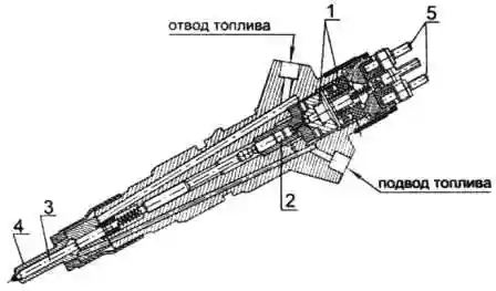
Nozzle: 1- solenoid valve; 2 - control valve; 3 - spray needle; 4 - atomizer; 5 - terminals
Injector (Fig. 6) is designed to inject fuel into the diesel cylinder and provide the necessary fuel spray.
Diesel engines use CRIN2 injectors manufactured by BOSH (Germany).
The required start of injection and the amount of fuel supply are provided by the action of the injector solenoid valve.
The injection start moment in the angle-time coordinates is set by the diesel electronic control system.
The formation of injector control signals by the electronic unit occurs on the basis of "reading" the signals generated by the crankshaft speed sensors and the input shaft of the injection pump drive gearbox (sensors 1 and 2 in Fig. 2.), installed in a coordinated relationship according to a certain scheme.
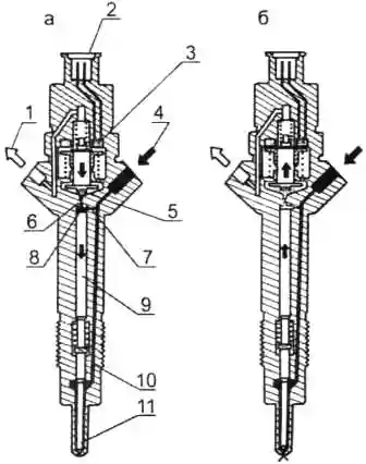
Principal diagram of the injector operation: 1 - fuel return line; 2 - electrical connection terminals; 3 - solenoid valve; 4 - high pressure line; 5 - valve ball; 6 - throttle opening for fuel outlet; 7 - throttle opening for fuel supply; 8 - control valve chamber; 9 - piston controlling the valve; 10 - channel for supplying fuel to the atomizer; 11 - needle and atomizer
The principle of operation of the nozzle is shown in Figure 7.
Fuel is supplied through the high-pressure line through the inlet channel 4 to the injector nozzle 11, as well as through the fuel supply throttle hole 7 - into the control valve chamber 8. Through the fuel outlet throttle hole, which can be opened by a solenoid valve, the chamber is connected to the return line. plum 1.
When the throttle hole 6 is closed, the hydraulic force acting from above on the piston of the control valve exceeds the force of fuel pressure from below on the cone of the atomizer needle.
As a result, the needle is pressed against the atomizer seat and tightly closes the atomizer holes. As a result, fuel does not enter the combustion chamber.
When the solenoid valve 3 is actuated, the solenoid armature moves up, opening the throttle hole 6.
Accordingly, both the pressure in the control valve chamber and the hydraulic force acting on the control valve piston are reduced.
Under the action of fuel pressure on the cone, the atomizer needle moves away from the seat, so that fuel enters the combustion chamber of the cylinder through the atomizer holes.
Control flow is the additional amount of fuel intended for lifting the needle, which, after use, is diverted into the fuel return line.
In addition to the control flow, there are fuel leaks through the atomizer needle and the control valve piston guide.
All this fuel is discharged into the backflow line, to which all other units of the injection system are connected, and returned to the fuel tank
The amount of injected fuel is proportional to the time the solenoid valve is turned on and the pressure in the rail, and does not depend on either the engine speed or the operating mode of the injection pump (time-controlled injection).
When the solenoid valve is de-energized, the armature is pressed down by the force of the valve locking spring and the valve ball 5 closes the throttle hole.
After closing the fuel outlet throttle, the pressure in the control valve chamber again reaches the same value as in the accumulator.
This increased pressure pushes down the control valve piston along with the atomizer needle.
When the needle fits snugly against the atomizer seat and closes its holes, injection stops.
Fuel coarse filter is used for preliminary fuel purification from mechanical impurities and water.
Due to the fact that the engine injection pump is not equipped with a manual fuel priming pump, which is necessary to fill the fuel system with fuel without air, the filter design must contain a manual fuel priming pump.
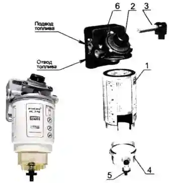
Coarse fuel filter "PreLine 270": 1 - coarse fuel filter; 2 - manual fuel priming pump; 3 - fuel heater; 4 - moisture separator; 5 - water outlet valve; 6 - air outlet plug
In fig. 8 shows a coarse fuel filter with a manual m fuel priming pump "PreLine 270".
The sludge is drained from the filter through tap 5, located at the bottom of the moisture separator 4.
When operating a diesel engine at an ambient temperature below -25°C, the filter housing must be equipped with a fuel heater 3.
Heater supply voltage - 24 V, power - 350 W. Connection: plus and ground.
The heater works autonomously, turns on and off automatically at temperatures below +5°C.
The fuel fine filter is used for the final purification of the fuel. The fine filter is non-separable.
The fuel, passing through the curtains of the paper filter element, is cleaned of mechanical impurities.
Diesel air supply system (Fig. 9) consists of an air filter, turbocharger, charge air cooler, pipes, pipelines and fastening clamps.
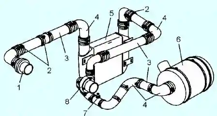
Engine air supply system: 1 - air supply pipe; 2 - clamps; 3 - pipe; 4 - branch pipe; 5 - charge air cooler; 6 - air filter; 7 - filter clogging indicator sensor; 8 - turbocharger
A dry-type air filter with replaceable paper filter elements is used to clean the air entering the cylinders.
The air filter (Fig. 10) consists of a housing 5, two filter elements 6 and 7, a cover 4 to ensure tightness, there are rubber gaskets.
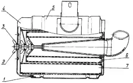
Air filter: 1 - sealing ring; 2 - lamb nut; 3 - washer; 4 - cover; 5 - body; 6 - filter control element; 7- main filter element
The small (inner) filter element provides air purification in case of mechanical destruction of the outer filter element.
Attention! The suction of uncleaned air into the engine cylinders, which occurs due to depressurization of the intake tract, leads to a sharp decrease in engine life.
To facilitate the control of air filter clogging, a sensor is installed between the filter and the turbocharger, and a signaling device on the instrument panel.
As the filter becomes clogged, the vacuum in the inlet pipeline increases and, upon reaching a value of 6.5 kPa, the signaling device is triggered, and the “Air filter clogged” warning lamp lights up on the instrument panel.
When the lamp lights up, clean or replace the filter element.
Turbocharger (Fig. 11) consists of a single-stage centrifugal compressor and a radial centripetal turbine.
Supercharge control occurs by bypassing part of the exhaust gases past the turbine wheel when the boost pressure exceeds a certain value.
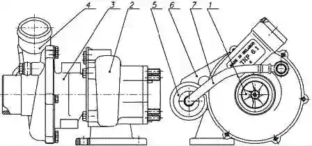
Turbocharger: 1 - rotor; 2 - turbine housing; 3 - bearing housing; 4 - compressor housing; 5 - actuator; 6 - bracket for fastening the actuator; 7 - air duct
A bypass valve is built into the turbine housing of a variable turbocharger.
The bypass valve lever is connected by an adjustable rod to the actuator connected by an air duct to the outlet pipe of the compressor housing.
Changing the length of the turbocharger actuator rod during operation is not allowed.
Disassembly and repair of the turbocharger during operation is not allowed and must be carried out in a specialized repair shop.


