Installing pistons with connecting rods
Lubricate the tops of the cylinders and the crankpins with engine oil.
Install the pistons with the connecting rods using the ring to install the piston with the piston rings into the cylinder liner, matching the pistons and cylinders
The marks on the pistons should point towards the flywheel.
Install the connecting rods on the crankshaft journals.
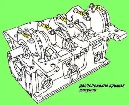
Install the connecting rod caps (see fig. 13).
Tighten the connecting rod cap stud nuts to 20 Nm + (45˚±5˚).
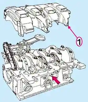
Install the oil pump drive sprocket, oil pump drive chain and oil pump (see Fig. 14).
Torque tighten the oil pump mounting bolts.
The tightness of the front cover of the engine block can be ensured either by installing a gasket or by installing the cover with Loctite 518 sealant.
The seating surfaces of the cylinder block and the front cover of the engine block must be clean, dry and free of oil, do not touch them with your hands.
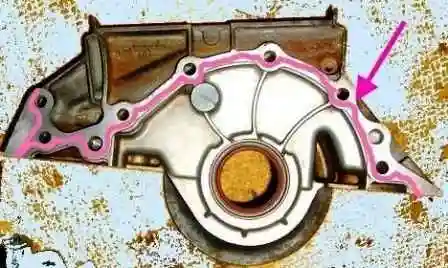
Loctite 518 is applied in a 1 mm wide strip, as shown in fig. 15.
Install the engine block front cover.
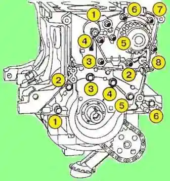
Tighten the cylinder block front cover bolts in the order shown in fig. 16.
The seating surfaces of the cylinder block and water pump must be clean, dry and free of oil, do not touch them with your hands.
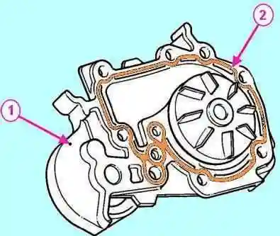
Install the water pump.
Instead of a gasket, use Loctite 518 sealant (1 mm wide strip), the place of application of the compound is shown in fig. 17.
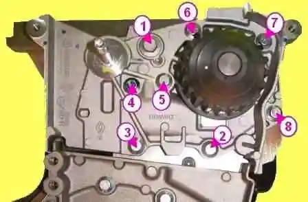
Note. Apply one or two drops of Loctite Frenetanch to the water pump mounting bolts (1) and (4) (see fig. 18).
Tighten the M6 bolts and M8 bolt in the order shown in fig. 18.
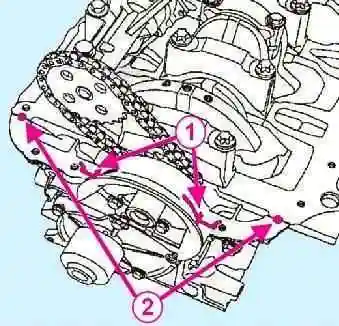
Apply four strips of Rhodorseal 5661 about 5 mm wide to the front and rear cover joints and to the cylinder block seating surfaces.
See 1, fig.19 for the location of the places where the composition is to be applied. for the back cover, the composition is applied in the same way.
Apply two drops of Rhodorseal5661, approximately 7 mm in diameter, to the seating surface of the front cover and cylinder block (2).
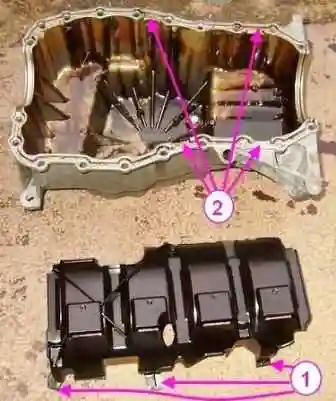
When installing the engine oil pan, make sure that the tongues (1) of the oil separator are installed in the grooves (2) (see fig. 20).
The cylinder block and engine sump must be aligned on the flywheel side to avoid damaging the clutch housing when connecting the engine to the transmission.
Install the oil softener.
Install oil pan with new gasket.
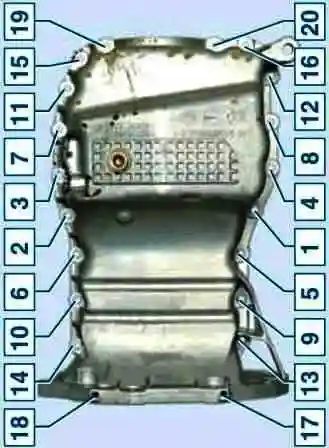
Tighten the oil pan bolts in the order shown in fig. 21:
- - First pass, Nm 8;
- - second pass, Nm 14.
Install the oil level sensor and tighten it to the required torque.
Tightening torques are indicated at the beginning of the article
Install the knock sensor and tighten it to the required torque.
Install the oil pressure switch and tighten it to the required torque.
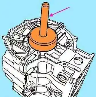
Press in the crankshaft rear oil seal using tool Mot1129-01 (see fig. 22).
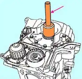
Press in the crankshaft front oil seal using tool Mot1385 (see fig. 23).
Replace the flywheel mounting bolts. Reuse of old bolts is not allowed.
Clean the crankshaft mounting flange and the threaded holes for the mounting bolts.
Check the technical condition of the flywheel.
Degrease the bearing surface of the flywheel and the counter surface on the crankshaft flange.
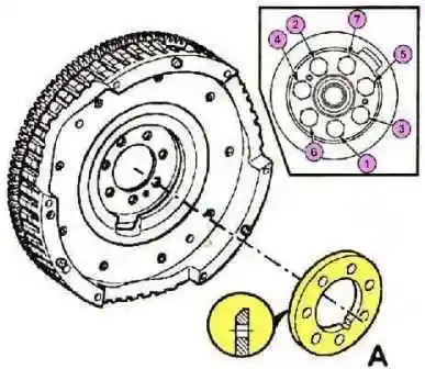
Install the spacer sleeve (A, fig. 24), the mounting position is chamfered to the flywheel.
Coat the threaded surfaces of the bolt threads with Loctite Frenetanch.
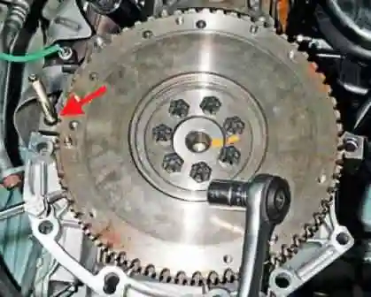
Tighten the mounting bolts by hand until they touch the flywheel, then lock the flywheel with lock Mot582-01 or Mot1677 (see fig. 25).
Tighten the flywheel bolts to 55 Nm.
Install clutch disc and clutch cover with pressure plate assembly.
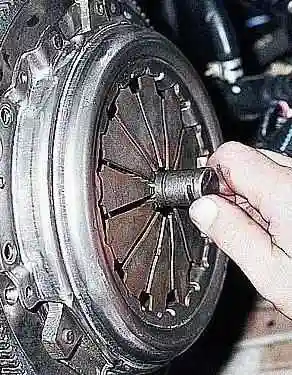
Center the driven disk using the Emb1518 mandrel (see Fig. 26), the mandrel is suitable for centering the VAZ vehicle discs.
Tighten the clutch cover bolts.
Remove the flywheel retainer.


