In the previous article, we covered the removal and installation of the engine cylinder head.
This article will describe how to check and repair the cylinder head of an ISF3.8 engine.
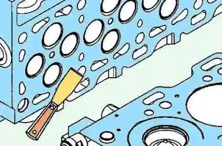
Remove the rest of the cylinder head gasket and clean the mating surfaces
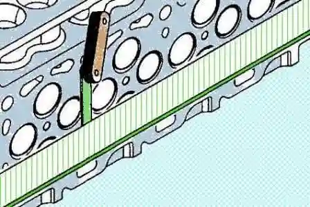
Using a precision ruler and feeler gauge, check the warping of the cylinder head.
Max warping:
- - along 0.305 mm
- - across 0.076 mm
If necessary, the cylinder head, cylinder block or cylinder head and cylinder block can be ground 0.5 mm.
After grinding, install the cylinder head repair gasket.
The cylinder head can be reground if the valve depth and injector protrusion remain within tolerance. If not, replace the cylinder head.
Using a dial indicator, determine the protrusion of the injectors at their highest point above the mating surface of the cylinder head.
Note: Install the rocker cover and injectors on the cylinder head before measuring injector protrusion.
Nozzle protrusion:
- - minimum 1.94 mm
- - maximum 2.47 mm
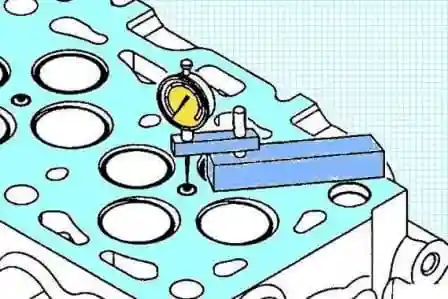
If the nozzle protrusion is out of specification, check the thickness of the sealing washer.
Nominal thickness 2.5 mm
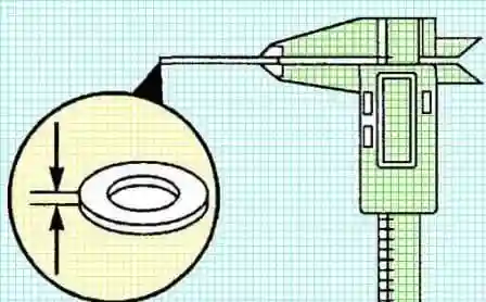
If the thickness of the sealing washer is correct, check for dirt and foreign particles in the nozzle hole.
Make sure there is no sealing washer stuck inside the hole.
Do not adjust nozzle protrusion by adding multiple washers.
If the nozzle protrusion is normal, remove the nozzle.
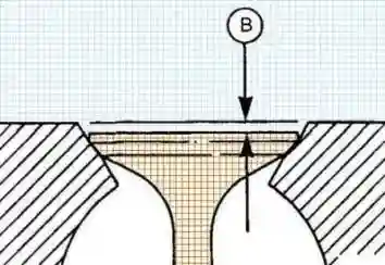
Using a dial indicator, check the valve installation depth in the cylinder head.
Note: When measuring valve depth, take two measurements at opposite points. Do not measure the depth at the center of the valve.
Valve installation depth:
Intake:
- - minimum 0.584 mm
- - maximum 1.092 mm
Graduation:
- - minimum 0.965 mm
- - maximum 1.473 mm
Note: Valve seat depth may be slightly increased after lapping.
Disassembly
Mark the valves according to the installation locations.
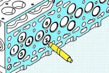
Compress the valve springs with the special tool (#4918866).
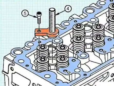
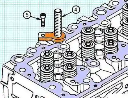
Install the screw (4) of the puller over the hole for the injector and insert the bolt (5) into the holes for the screw of the clamp removed from the cylinder head.
Tighten the bolts (5).
Tightening torque 5 Nm
Apply anti-seize compound to the threads of the screw (4) of the puller.
Be sure to read and follow the precautions on the label.
The valves are at different distances from the nozzle hole.
It is necessary to align the grooves in the valve spring compression tool plate with these springs.
Install the valve spring compressor plate (1) onto the screw (4) of the puller and align the grooves in this plate with the valve springs.
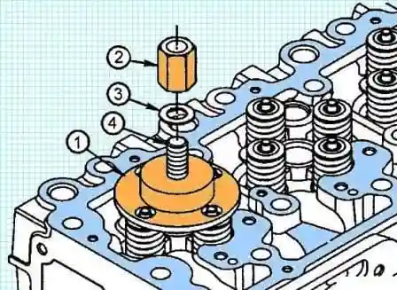
Install the washer (3) and nut (2) on the screw (4) of the puller.
Turn the nut (2) clockwise to compress the valve springs.
Note: Valve springs are compressed and may fly out when removed. Use safety glasses.
Continue to turn the nut (2) clockwise until the valve cotters can be removed, e.g. with a magnetized screwdriver.
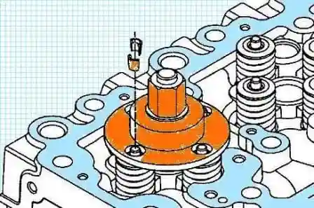
Remove cotters and valve spring compressor
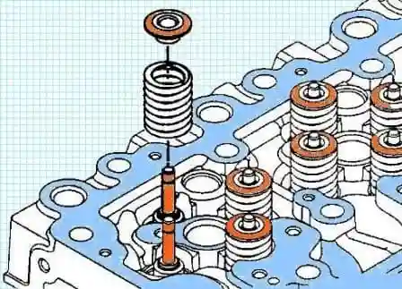
Remove the poppets and valve springs
Remove the valves.
Store the removed parts in the order they were removed from so that they can be reinstalled.
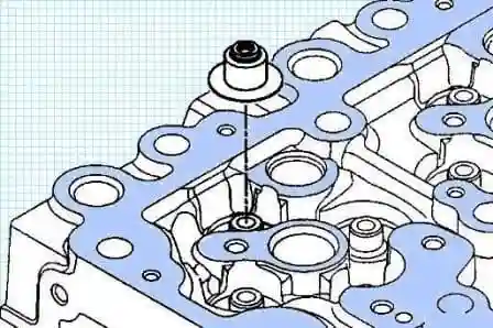
Remove the valve stem seals.
Remove the valve seats if necessary.
а) A groove is provided in the valve seat for installing a valve seat puller, made in the form of an impact slider.
If there is no recess, turn it with a special tool (No. 3376405).
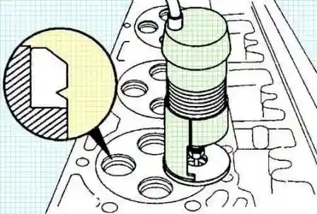
Using an inertial puller and tool (#3165170), remove the valve seat.
The valve seat puller assembly must be installed at right angles to the cylinder head.
Insert the extractor into the valve seat and turn the T-handle clockwise until the extractor slightly compresses the valve seat.
Install the puller into the valve seat groove.
Turn the T-handle so that the puller is under the valve insert.
By hitting the top nut with the slider, remove the valve seat.
Turn the T-handle counterclockwise to remove the seat from the puller.
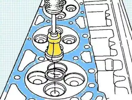
Clean the nozzle hole.
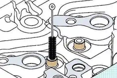
Use a soft brush to clean the valve stem guide.
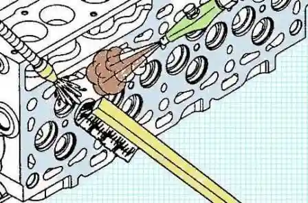
If necessary, remove deposits in the cooling channels.
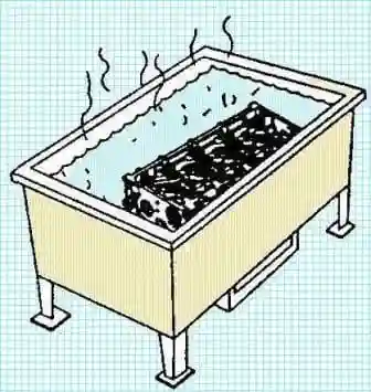
Note: deposits can be removed from the acid tank by first removing the expansion plugs
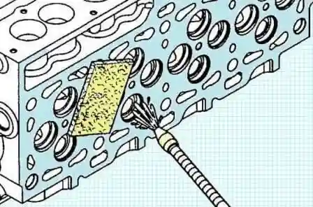
Clean the mating surface with solvent and an abrasive stone
Make sure there are no signs of wear that can be seen with a fingernail at a distance of 3.2 mm from the edge of the combustion chamber.
The presence of wear outside this area does not affect the tightness of the combustion chamber and the cylinder head can be reused.
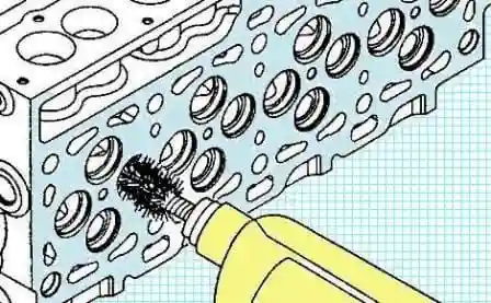
Remove carbon deposits from the valve well with a high quality wire brush clamped in a drill chuck or grinder attachment.
Use a wire brush and solvent to remove deposits from valve seat holes.
Dry with compressed air.
Finally clean the cylinder head.
- a) Clean the cylinder head with hot soapy water.
- b) Rinse the cylinder head with clean water.
c) Dry the cylinder head with compressed air.
Check the cylinder head for cracks.
Take a close look at the following places:
- - hole for the nozzle;
- - combustion chamber surface;
- - valve seats;
- - valve guides.
Replace the cylinder head if there are deep cracks.
Small and shallow cracks are acceptable.
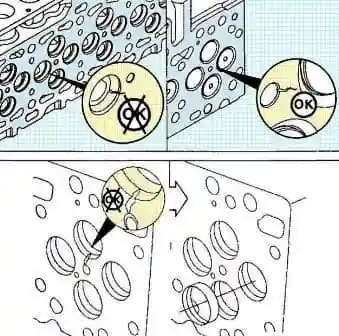
Measure the diameter of the valve seat hole in the cylinder head if the seat was removed.
Valve seat hole diameter 34.837 - 34.863 mm
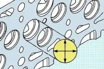
If the diameter is larger than specified, bore the hole for the valve seat to the repair size (0.254 mm or 0.508 mm)
Measure the inside diameter of the valve guides.
Valve guide inner diameter 7.027- 7.077 mm
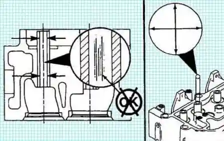
Replace the cylinder head if the valve guide bore is worn excessively or the valve guides are damaged.
Clean the valve heads with a soft wire circular brush.
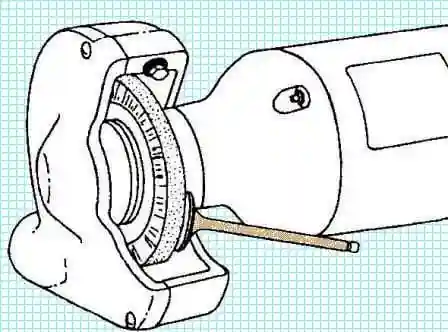
Buff the valve stems with an abrasive pad (3823258) and thinner
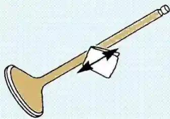
Check the valves.
Check the valves for excessive head, stem and stem tip wear, bending and deformation.
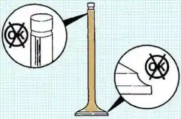
Check the valves for damage to the cracker grooves
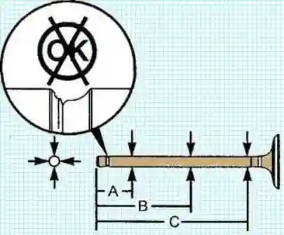
Measure the diameter of the valve stem in three places at the following distances: A -40 mm, B - 90 mm, C - 140 mm.
Valve stem diameter 6.96-7.01 mm
Check the valve springs.
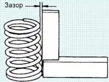
Using a metal square (90°), check that the valve spring is not perpendicular as shown.
Maximum allowed non-perpendicularity 1.5 mm
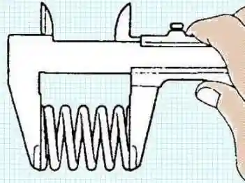
Measure the free length of the spring with a caliper:
Nominal free length 47.75 mm
If the length of the spring differs from the nominald, replace the valve spring.
Measure the length of the valve spring under load.
Nominal spring length (at 320.8-358.8 N) 35.33 mm
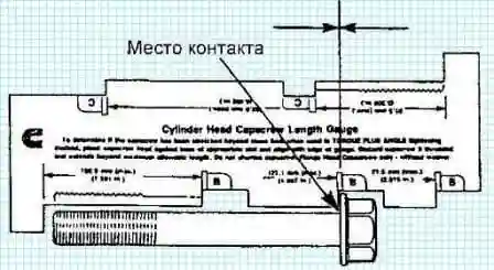
Check the cylinder head bolts.
Check the free shaft length of the bolt. Maximum bolt length 152.1 mm
If the bolt is longer than the maximum length, replace the bolt.
For verification, you can use the template (#3164057)
Assembly
Install new valve seats.
Note: Valve seats must not be reinstalled.
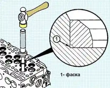
valve seat installation
When installing, note that the inlet and outlet valve seats are different.
Valve seat angle:
- - inlet 30°
- - outlet 45°
Use a new valve for each inlet and outlet valve seat by pressing it in, and if this fails, use a special hammer to install new valve seat inserts.
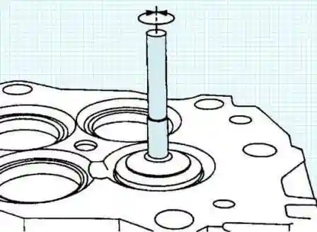
Lap the valves onto the valve seats.
- a) Lubricate the valve stems with SAE 15W-40 engine oil before installation.
- b) Apply a thin, even layer of fine lapping abrasive (23375805 or equivalent) to the valve disc.
- c) Using an electric or manual lapping tool, apply force to the center of the valve.
Turn the valve clockwise and counterclockwise.
Continue lapping until there is good contact between seat and valve.
- e) Remove the lapping abrasive.
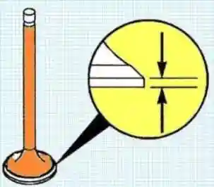
- f) Check the thickness of the valve disc.
Minimum valve disc thickness 0.79 mm If less than minimum thickness, replace valve.

Install the valves, lubricating their stems with engine oil.
When installing previously removed valves, install them in the same places from which they were removed.
Install new valve stem seals.
Install valve stem seals of the same type and color as previously installed.
Colors used:
- - green exhaust valves
- - yellow inlet
- - exhaust valves
- - Brown intake and exhaust valves
Lubricate the valve stem seals with engine oil.
Using a drift, install new valve stem seals.
Hold the valve with your hand during installation.
Install poppets and valve springs.
Install crackers.
Compress the valve springs with the special tool (#4918866).
Install the screw (4) of the puller over the hole for the injector and insert the bolt (5) into the hole for the screw of the clamp removed from the cylinder head.
Tighten the bolts (5).
Tightening torque 5 Nm
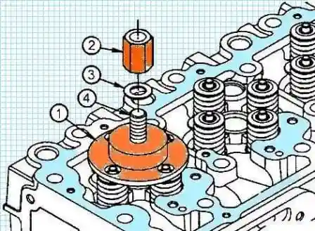
Apply anti-seize compound to the threads of the screw (4) of the puller.
Note: the valves are at different distances from the nozzle hole.
It is important to align the grooves in the valve spring compressor plate with these springs.
Install the valve spring compressor plate (1) onto the screw (4) of the puller and align the grooves in this plate with the valve springs.
Install washer (3) and nut (2) on the screw (4) of the puller.
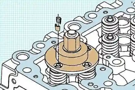
Compress the valve springs and install the cotters.
Note: Apply assembly lubricant (#3163087 or equivalent) to the cotter pins to help hold them in place until the valve spring compressor is removed.
Remove the valve spring compressor.
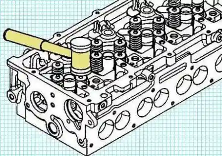
Tap the ends of the valves with a plastic-headed hammer to ensure a secure fit with crackers.
Disassembly of rocker arms
Note: install the rocker parts in the places where they were removed from.
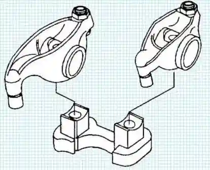
Remove the rockers from the support.
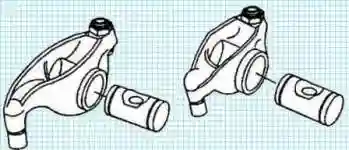
Remove the axles from the rocker arms.
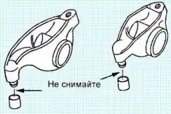
Do not remove the nest from the end of the rocker. If it is damaged, replace the rocker
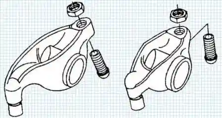
Remove the locknut and adjusting screw
Checking the rocker arms
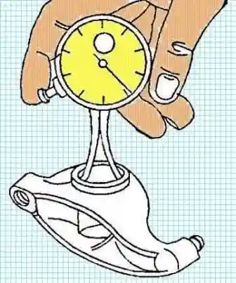
Measure the inner diameter of the rocker hole.
Maximum diameter 22.027 mm
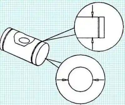
Measure the outside diameter of the rocker shaft.
Minimum diameter 21.965 mm
Assembly of rocker arms
Install the rocker arm assembly.
Note: all parts of the rocker arms must be installed in the places where they were removed from.

Fully tighten the adjusting screws, then tighten the locknut
Lubricate the rocker shafts with engine oil.

Install the axles in the rocker arms.
Place the rockers on the support.
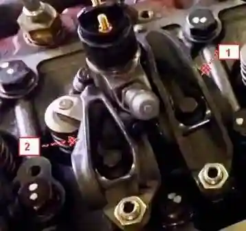
Note: Do not mix up intake and exhaust valve rockers
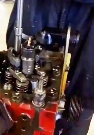
Install the valve bridges where they were removed.
Install rocker arms with supports assemblies in the places where they were removed.
Install the support bolts. Tightening torque 36 Nm


