Engine disassembly was discussed in the article - "Engine disassembly"
Defection of engine parts was discussed in the article - "Defection of engine"
In this article we will consider the main points of assembling the VAZ-2112 engine.
Before assembly, all engine parts must be washed and defective.
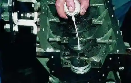
Before installing the upper main bearing shells with an aerosol carburetor cleaner, we clean the piston cooling nozzles.
Install the liners in the bed of the main bearings.
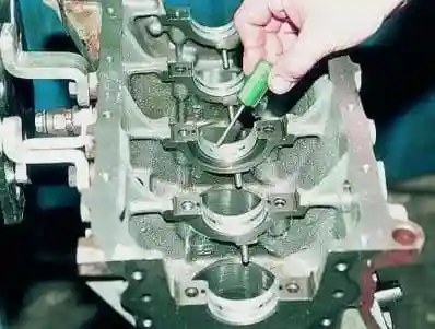
In this case, the fixing protrusion of the liner should enter the groove of the bed.
In the first, second, fourth and fifth beds (counting from the camshaft drive), install liners with grooves, and in the third without a groove.
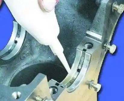
Lubricate the liners with engine oil
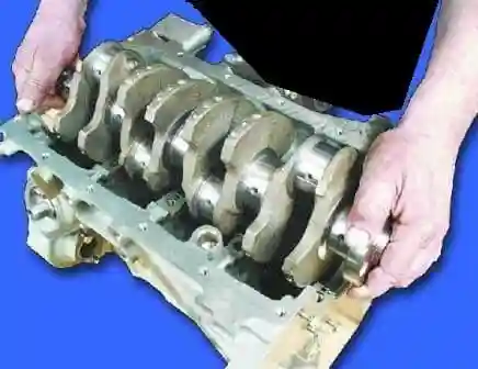
Lubricate the crankshaft journals with engine oil and lay the shaft in the bed of the main bearings.
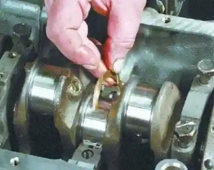
We insert thrust half rings lubricated with engine oil into the grooves of the third main bearing support.
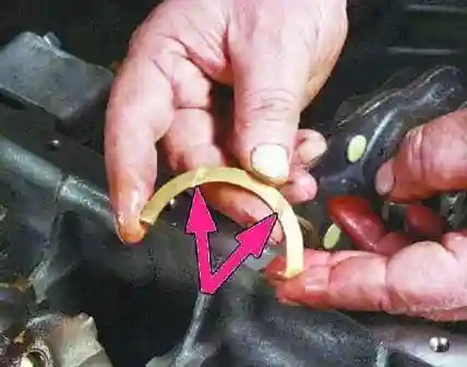
The surfaces of the semi-rings with an anti-friction coating (grooves are made on them) should face the cheeks of the crankshaft.
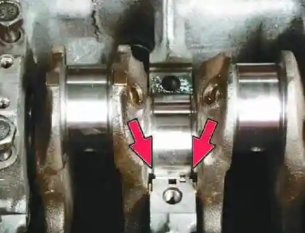
Turn the half rings so that their ends are flush with the ends of the bed.
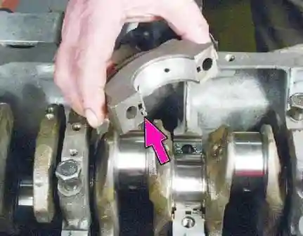
We install the main bearing caps in accordance with the marks made on their outer surface (the caps are counted from the timing belt drive side).
In this case, the locks of the upper and lower shells of each main bearing must be located on the same side.
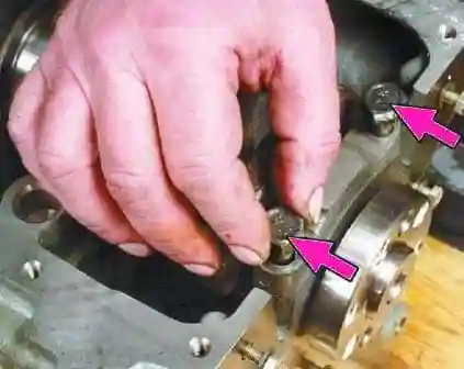
We wrap the bolts of the covers without tightening them
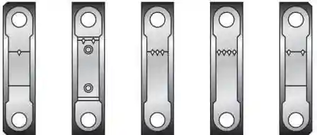
Marks on main bearing caps
Tighten the cap bolts to 69-84 Nm (6.9-8.4 kgf m).
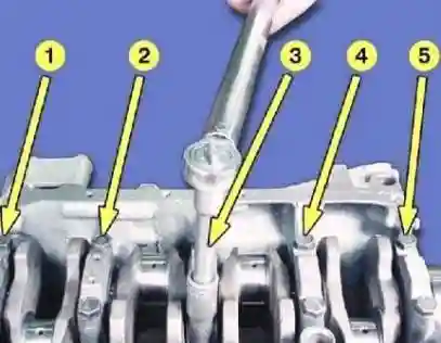
First we tighten the bolts of the third cover, then the second and fourth, then the first and fifth.
After tightening the bolts, turn the crankshaft - it should rotate easily, without jamming.
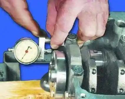
Measure the axial clearance of the crankshaft.
It should be within 0.06-0.26 mm.
If the gap exceeds 0.26 mm, replace thread resistant half rings
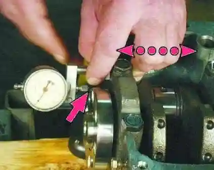
To measure the end clearance of the crankshaft, install the indicator so that its leg rests on the shaft flange.
Move the crankshaft away from the indicator and set the indicator to 0.
Move the crankshaft to the opposite side.
The indicator will show the amount of clearance.
A steel-aluminum semi-ring is placed in front (from the side of the crankshaft pulley), and a metal-ceramic one is placed in the back.
Rings are produced with nominal and increased by 0.127 mm thickness.
When the axial clearance of the crankshaft exceeds 0.35 mm, one or both half rings change (the nominal clearance is 0.06-0.26 mm).
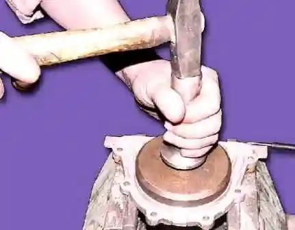
We press the crankshaft rear oil seal into the holder with a mandrel until it stops.
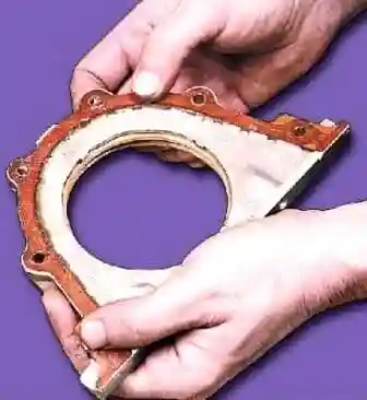
Glue the holder gasket to the gland holder with grease for ease of installation
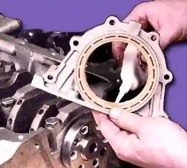
Lubricate the sealing lip with engine oil.
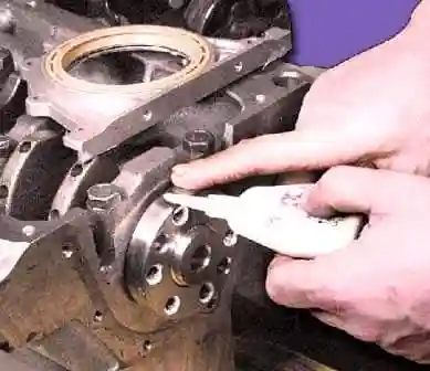
Lubricate the crankshaft flange with engine oil.
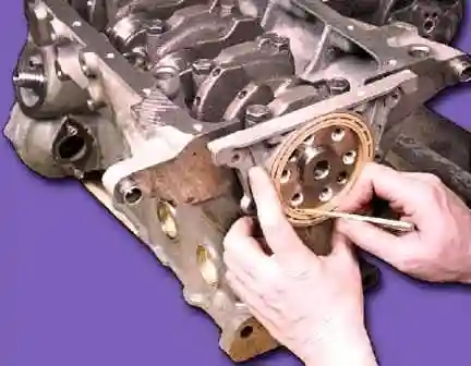
We put the oil seal with the holder on the crankshaft flange and carefully fill the working edge of the oil seal with a pointed stick
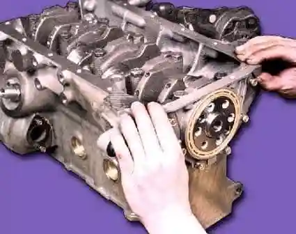
We shift the holder with the gland along the flange until it stops and bait the fastening bolts
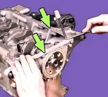
Adjust the holder so that its upper plane coincides with the plane of the block
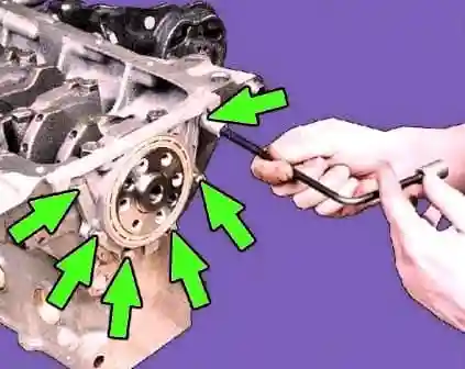
Tighten the six mounting bolts of the holder
Preparing the oil pump for assembly.
We press the front crankshaft oil seal into the pump housing.
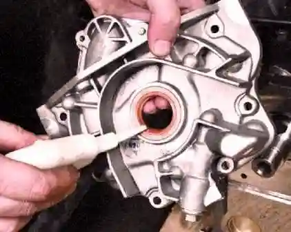
Lubricate the sealing lip with engine oil
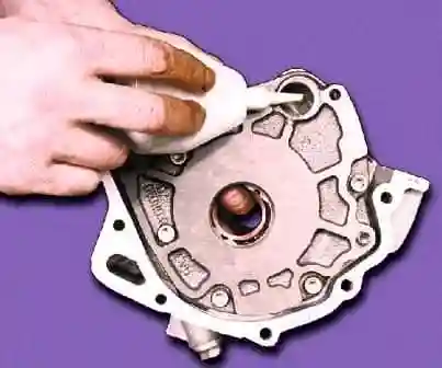
Lubricate the gears of the oil pump with engine oil, pouring oil through the hole for the oil receiver.
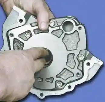
Turn the gears of the oil pump several times by the protrusions of the drive gear.
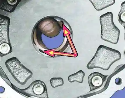
Turn the oil pump drive gear so that the projections on the drive gear match the flats on the crankshaft.
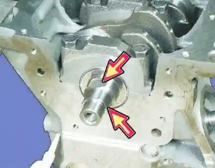
Flats on the crankshaft
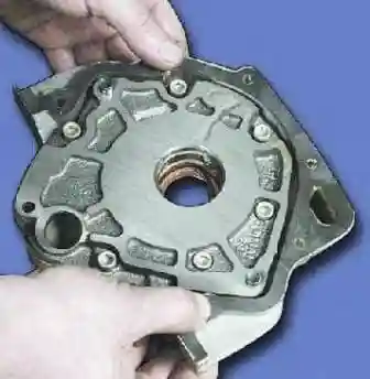
We glue the sealing gasket to the pump with grease for ease of installation.
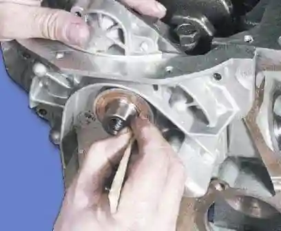
Push the pump with the oil seal onto the crankshaft up to the seat on the shaft. Then, with a pointed stick made of soft wood, carefully tuck the lip of the stuffing box onto the shaft neck.
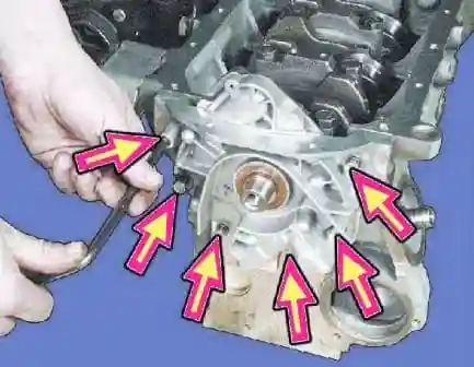
Carefully slide the oil pump along the shaft until it stops and screw on the mounting bolts
Adjust the position of the pump so that its upper plane coincides with the plane of the block.
Tighten the six fastening bolts with a torque of 8.5-10.0 Nm (0.85-1.0 kgf m).
When assembling the connecting rod and piston group, it is necessary that the piston pin, lubricated with engine oil, enter the piston hole with the force of pressing the thumb and not fall out of the piston when the finger is vertical.
We install rings on the pistons and arrange them as follows:
- - the lock of the upper compression ring is oriented at an angle of about 45 ° to the axis of the piston pin
- -lock of the lower compression ring - at an angle of 180° to the axis of the lock of the upper ring.
- - oil scraper ring lock - at an angle of 90 ° to the axis of the upper compression ring lock.
Set the lower compression ring with the groove ("scraper") down.
If the ring is labeled "TOP" or "TOP" - the ring is placed with the label up.
When installing the oil scraper ring, we place the expander joint on the side opposite to the ring lock.
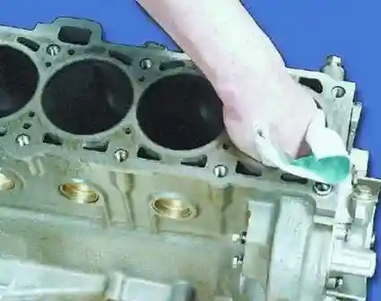
Wipe the cylinder mirrors
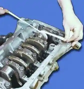
Wipe the connecting rod journals of the crankshaft
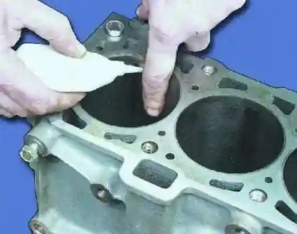
Lubricate the mirror of the first cylinder with engine oil
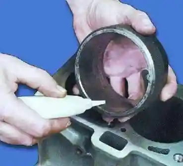
Lubricating the mandrel for installing pistons
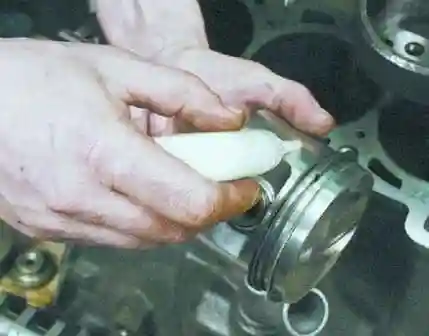
Lubricating the piston of the first cylinder
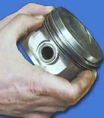
We breed the locks of the rings as above
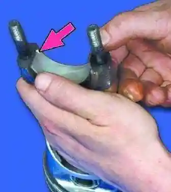
Insert the liner into the lower head of the connecting rod. The protrusion on the bushing must fit into the groove of the connecting rod head
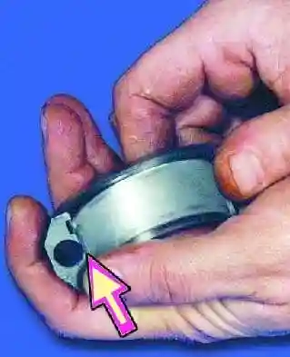
Insert the liner into the connecting rod cap so that the protrusion on the liner fits into the groove of the connecting rod cap
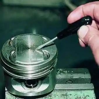
When installing the pistons in the cylinders, the arrow on the piston crown must point towards the timing drive.
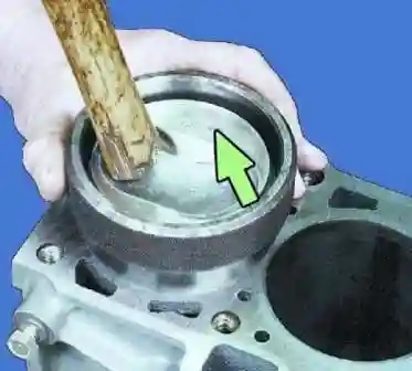
Insert the piston assembly with the connecting rod into the mandrel.
Point the arrow to the pore screw towards the oil pump and slowly push the piston with the wooden handle of the hammer
We control the correct position of the connecting rod bearings.
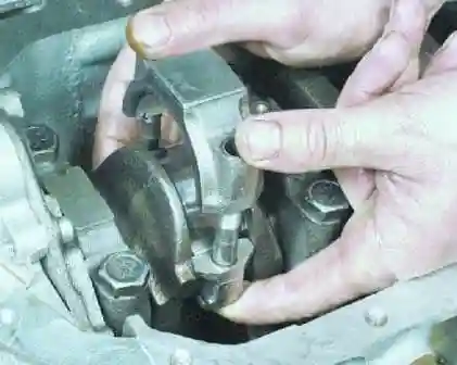
Lubricate the liners and install the connecting rod cover in accordance with the marking.
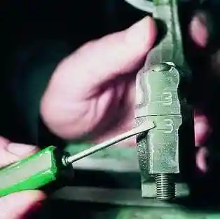
The connecting rod caps are installed so that the cylinder numbers on the cap and the connecting rod are on the same side
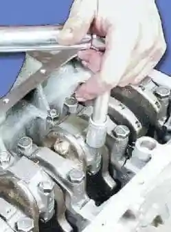
Tightening the cover fastening nuts.
In the same way, install and tighten the covers of the remaining connecting rods.
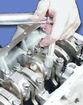
Tighten the connecting rod cap nuts to 44-54 Nm (4.4-5.4 kgf m) with a torque wrench.
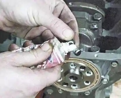
Before installing the flywheel, lubricate the threads of the flywheel mounting bolts with a thin layer
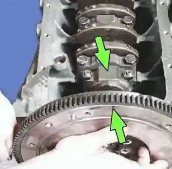
Install the flywheel so that the mark on the flywheel is opposite the connecting rod cover of the fourth cylinder, since the mounting bolts are asymmetrically located
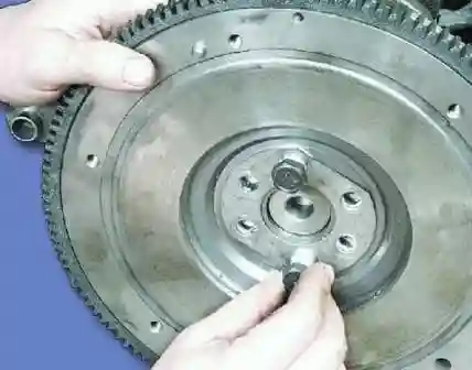
Install the lock washer and wrap the flywheel
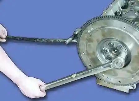
We tighten the flywheel mounting bolts to a torque of 62-89 Nm (6.2-8.9 kgf m), keeping the flywheel from turning
We will consider further engine assembly in continuation of this topic


