

We are dismantling the cylinder head for subsequent repair or for replacement.
When dismantling, the cylinder head parts should be laid out in order, bearing in mind their further use.
Removal of the cylinder head was covered in the article ‘How to dismantle the engine’.
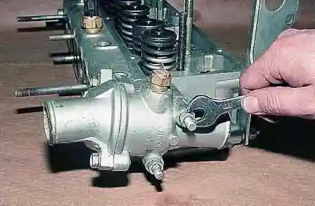
Using a 13 mm spanner, slacken the nuts securing the thermostat housing.
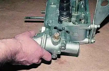
We remove the thermostat housing from the cylinder head.
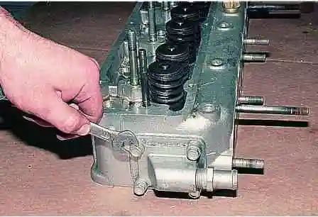
Using a 12 mm spanner, slacken the four bolts securing the rear cover of the cylinder head.
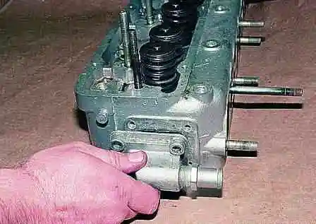
We remove the rear cover of the cylinder head.
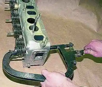
We remove the valves using a valve spring compressor. This compressor has a stop for the valve.
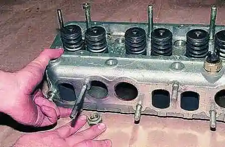
If no such compressor is available, place a suitable stop under the valve — a thick rubber washer or a wooden block will do.
The valves must be marked or laid out in order so that they can be refitted in their original positions during reassembly.
We fit a special tool for compressing the valve springs onto the cylinder head.
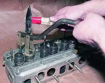
We compress the valve spring with the tool. If the valve retainer sticks, tap the tool stop with a hammer.
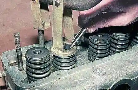
Holding the springs compressed, we extract the two collets with tweezers or a thin screwdriver.
Then, gradually releasing the pressure on the tool handle, we fully release the valve springs.
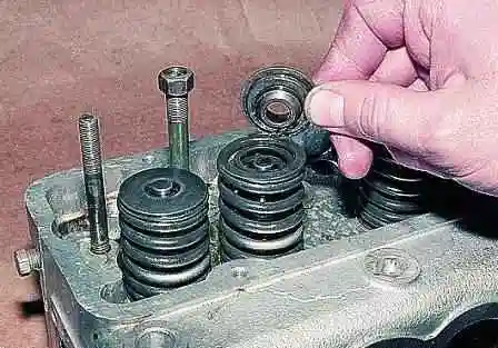
We remove the tool and take off the valve retainer.
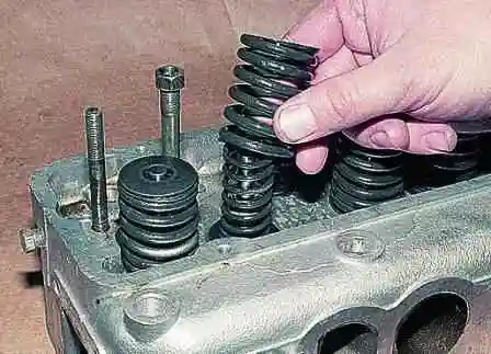
We extract the two springs.
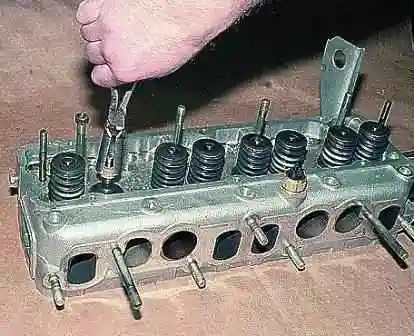
With pliers, carefully remove the valve stem seal from the guide.
When removing, twist the seal slightly to make it easier to take off. Careful: the guide is very fragile!
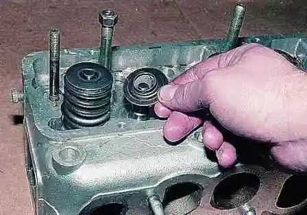
We remove the support washer.
We turn the cylinder head over.
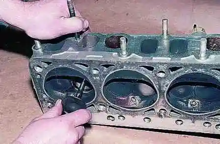
We withdraw the valve from the cylinder head.
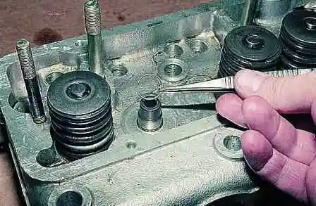
If the guide wear is large and exceeds 0.25 mm, prise out the circlip with a screwdriver and remove it.
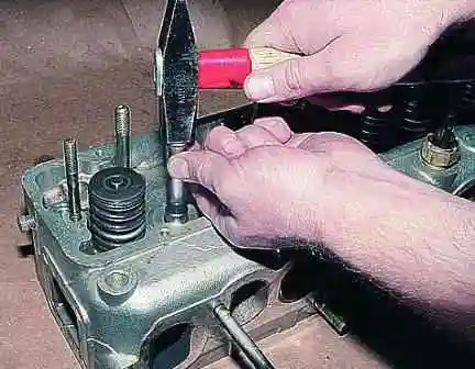
Using hammer blows through a drift, we drive out the guide.
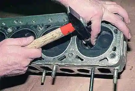
Fitting a new guide: cool the new guide in dry ice or in the freezer, heat the cylinder head to 150–190 °С and press the guide in.
The guide must protrude 20 mm above the cylinder head.
After pressing in the guides, they must be reamed with a special reamer to the required size.
After that, the valves must be ground into their seats. To do this:
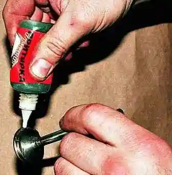
We apply grinding paste to the valve face and insert the valve into the corresponding guide in the head.
We attach a special grinding tool to the valve stem.
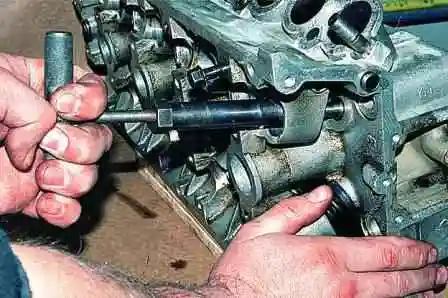
We press the valve against its seat and turn the valve in both directions.
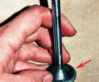
We continue grinding until the valve face becomes matt and clean over its entire length and width.
We wipe the valves free of paste residue.
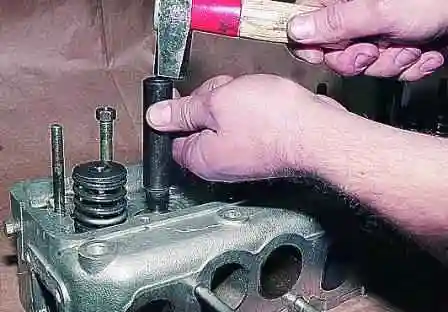
We fit the new valve stem seals using a drift.
Reassembling the cylinder head
We reassemble the cylinder head in the reverse order of dismantling.
The cylinder head is reassembled in the reverse order of dismantling.
Before fitting, lubricate the stem seals, valve stems and rocker shaft with engine oil.
The valves are fitted in accordance with the marks made during dismantling.
The thermostat housing gasket and the rear cover gasket are to be fitted with «Hermesil» type sealant.
A more detailed fault inspection is covered in the article ‘Inspection and fault diagnosis of the cylinder head’.


