The steering of the car is rack and pinion, with hydraulic booster. Steering rack-and-pinion
In the crankcase of the steering mechanism, a drive gear is installed on two bearings, which meshes with the rack.
When the steering wheel is turned, the steering column shaft is rotated, which is connected to the drive gear through the intermediate shaft (at the ends of which there are cardan joints).
The gear moves the rack, which, through the steering rods with tips and the steering knuckle levers connected to them, turns the steered wheels of the car.
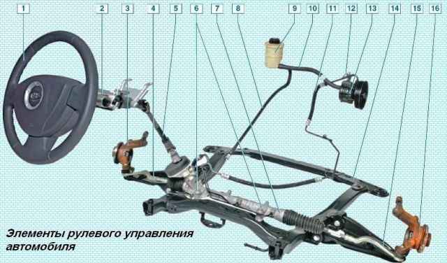
Elements of the steering of the car: 1 - steering wheel; 2 - steering column; 3 - left knuckle assembly with hub; 4 - left tie rod end; 5 - intermediate shaft; 6 - bolts for fastening the crankcase of the steering mechanism to the subframe; 7 - steering gear housing; 8 hydraulic booster drain line; 9 - hydraulic booster reservoir; 10 - hydraulic booster filling line; 11- pressure line of the hydraulic booster; 12 - hydraulic booster fluid pressure sensor; 13 - hydraulic booster pump; 14 - subframe; 15 - right tie rod end; 16 - right steering knuckle assembly with hub
The steering box is attached to the subframe with two bolts.

In the steering gear housing, the rack is pressed against the drive gear through the stop.
The side clearance between the gear and the rack is adjusted by rotating the adjusting plug.
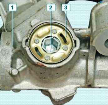
Adjustment is carried out only when the steering mechanism is assembled at the factory.
In operation, the gap cannot be adjusted.
The steering gear consists of two steering rods connected to the steering gear rack and steering knuckle levers.
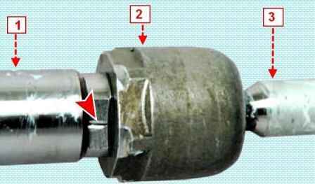
Each rod is attached with its inner end to the steering rack through a non-separable ball joint - the threaded tip of the hinge is screwed into the hole in the rack.
In the middle part of the steering rod there is a hexagon turnkey “13”, and on the outer end there is a thread (right), on which the rod end is screwed.
The tie rod end has a non-separable ball joint that does not require replenishment of the lubricant supply, which is embedded inside it for the entire service life.
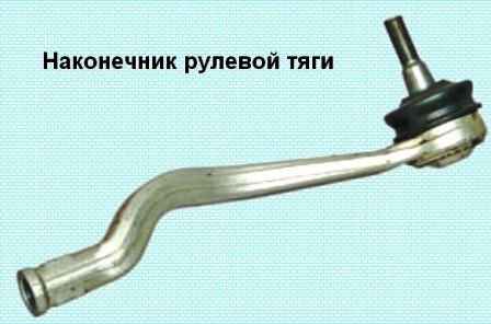
The right and left tie rods are the same, but the ends are different.
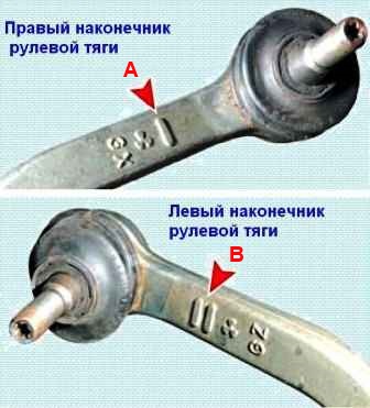
The connection of the steering rack and the tie rod ball joint is protected from dirt and moisture by a corrugated rubber boot.
The cover is fixed with a plastic clamp on the steering gear housing, and the cover is held on the steering rod due to the elasticity of the rubber - while the narrow belt of the cover must coincide with the groove made on the steering rod.
When assembling the steering mechanism at the factory, the threaded connection of the tie rod end with the rack is secured against loosening with an anaerobic fixing sealant.
The steering column is safety, with a steering wheel tilt adjustment mechanism.
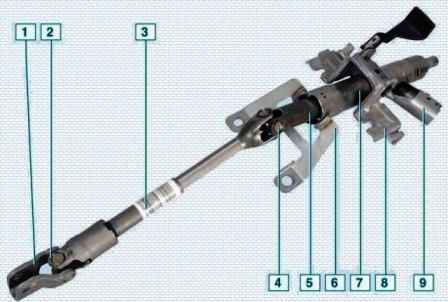
Steering column with intermediate shaft: 1 - coupling; 2 - lower universal joint; 3 - intermediate shaft; 4 - upper universal joint; 5 - steering column shaft; 6 - front bracket for mounting the column; 7 - pipe; 8 - rear column mounting bracket; 9 - ignition switch socket
The steering column shaft is attached to the steering gear via an intermediate shaft with two cardan joints.
The intermediate shaft is made of composite to ensure safety.
In the event of a frontal impact of the vehicle during an accident, the steering column must not move towards the driver.
This is achieved by a spline connection in the middle of the shaft.
A steering wheel is mounted on the splines in the upper part of the steering column shaft.
The steering column is attached to the cross member bracket located under the instrument panel.
A hydraulic power steering (power steering) is installed on the car.
The hydraulic booster system includes: a steering gear, a pump, a reservoir for working fluid and connecting pipes of the lines.
A liquid pressure sensor is installed in the discharge line to provide a signal to the electronic engine control unit.
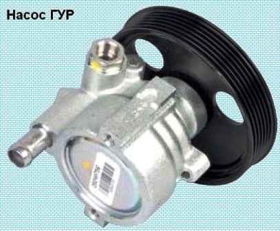
The pump is driven by a belt from the accessory drive pulley.
Hydraulic fluid from the reservoir enters the pump, and from it it is supplied under high pressure to the distribution device, located in a separate housing on the steering gear housing and mechanically connected to the steering column shaft.
The switchgear is designed to monitor the mismatch of the angles of rotation of the steering wheel and the drive gear shaft of the steering mechanism and strictly dosed change the fluid pressure in the chambers of the actuator.
A hydraulic cylinder piston is fixed on the gear rack of the steering gear.
When the steering wheel is turned, the switchgear connects one of the hydraulic cylinder chambers to the pump discharge line, and the other chamber to the drain.
At the same time, the piston of the hydraulic cylinder, due to the pressure difference of the working fluid, moves the rack to the left or right and turns the steered wheels of the car through the steering rods and fist levers.
If the hydraulic booster fails, the ability to drive the car remains, but the force on the steering wheel increases.
To control the fluid level in the hydraulic booster reservoir, MIN and MAX marks are applied to its translucent body.
Possible steering problems and remedies
Cause of malfunction Remedy
Increased steering wheel play
Loose tightening of the nuts securing the ball pins of the rod ends - Tighten the nuts
Increased clearance in ball joints of tie rod ends - Replace tie rod ends
Large gap between rack stop and nut - Adjust clearance in steering gear
Steering wheel is hard to turn
Auxiliary drive belt broken or loose - Check the condition of the belt. Change the belt
Low level of fluid in the power steering reservoir - Replace the pump, bleed the system
The bearing of the front shock strut upper support is damaged - Replace the bearing of the support
Steering rack bush or stop damaged - Replace damaged parts or steering assembly
Front tire pressure low - Set correct tire pressure
Tie rod joints damaged - Replace tie rod ends
Steering gear bearings damaged - Replace bearings or steering gear assembly
The angles of the front wheels are violated - Adjust the angles of the wheels
Loose steering gear - Tighten the steering gear bolts to the subframe
Uneven resistance to steering wheel rotation with the engine running
Air in hydraulic steering system - Bleed hydraulic system
Insufficient power steering fluid pressure - Replace power steering pump
Steering gear spool sticking - Replace steering gear


