In the article, we will consider the replacement of the front suspension arm, the replacement of parts of the anti-roll bar, the repair of the steering knuckle.
Removing and installing the subframe is discussed in the article - Removing and installing the subframe of a Renault Sandero car
Removal and repair of the shock strut is discussed in the article - Repair of the shock strut Renault / Dacia Sandero
Removing and installing the front suspension arm
Tools will be required: keys for 13, 18, Torx T30
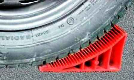
We prepare the car for the task, brake it with a parking brake and install shoes under the rear wheels.
We loosen the wheel bolts, from the side of the work being performed, raise the front of the car and install it on reliable supports.
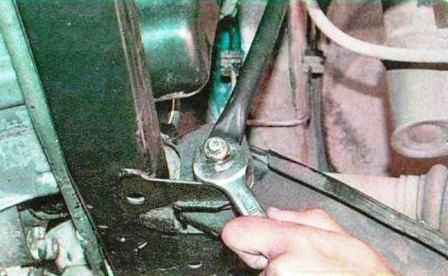
We unscrew the nut of the lower fastening of the connecting rod
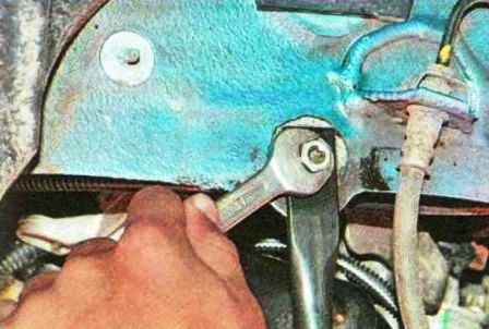
We unscrew the bolt of the upper fastening of the connecting rod
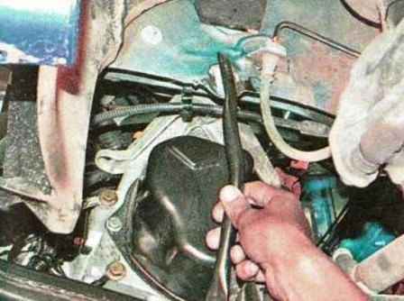
Remove traction
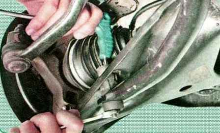
If the car is equipped with an anti-roll bar, unscrew the nut of the stabilizer bar bolt and remove the bolt.
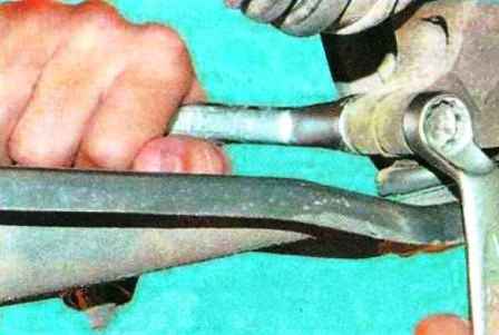
We unscrew the nut of the coupling bolt connecting the steering knuckle with the ball joint
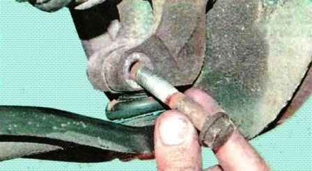
Remove the tie bolt from the hole
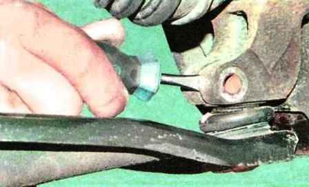
Open the terminal connection with a screwdriver
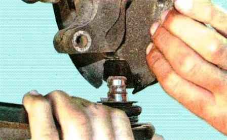
Remove the ball joint pin from the steering knuckle hole
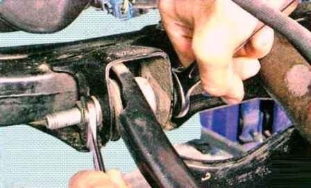
Unscrew the nut of the bolt securing the front arm silent block to the subframe (Fig. 10) and remove the bolt
We also unscrew and remove the bolt of the rear silent block of the lever to the subframe
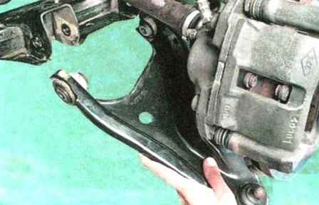
Remove the front suspension arm
Install the lever in reverse order.
We tighten the nuts of the bolts for fastening the silent blocks of the levers to a torque of 105 Nm (10.5 kgcm), the connecting rod bolt to a torque of 21 Nm (2.1 kgcm), the connecting rod nut and the nut of the terminal connection of the steering knuckle with a ball joint to a torque of 62 Nm (6, 2 kgcm).
After replacing the lever, we check the wheel alignment.
Replacing anti-roll bar parts
The stabilizer is installed on modifications with an engine K4M
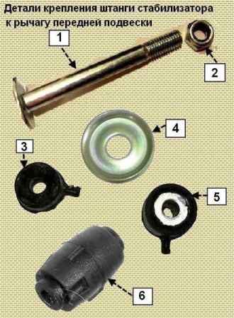
Tools required: wrenches 10, 13, Torx T40, socket 18
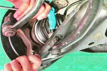
Unscrew the nut of the stabilizer bar bolt
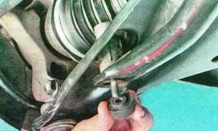
Remove the lower silent block
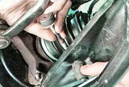
Remove the rubber bushing and remove the stabilizer bar mounting bolt
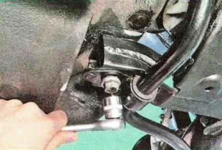
Remove the rear subframe bolt
If you unscrew both rear bolts of the subframe at the same time, you need to install stops under the subframe
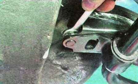
Unscrew the nut securing the stabilizer bar bracket
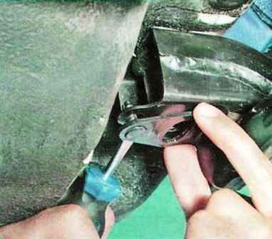
We pry off the rod fastening bracket with a screwdriver
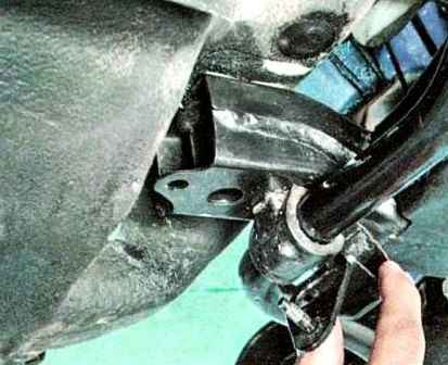
Remove the stabilizer bar bracket
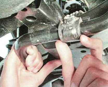
Remove the rubber cushion
We also remove the second stabilizer bar mounting bolt and mounting bracket
Remove the stabilizer bar from the car
Install parts in reverse order
Removing and installing the steering knuckle
Tools will be required: wrenches 18, Torx T40, Torx T30, socket 30, wrench, wrench for wheel bolts.

We put the car on the handbrake and put stops under the rear wheels
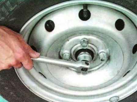
Loosen the wheel bolts and the wheel hub nut.
Raise the front of the car with a jack and place it on the stops.
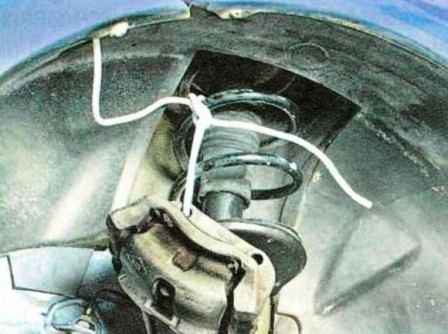
Remove the front wheel brake caliper and fix it with wire to the shock strut spring
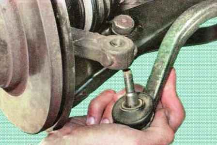
Unscrew the nut and take out the finger of the balls of the tie rod end from the steering knuckle boss
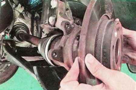
Remove the brake disc
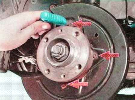
We unscrew the three bolts securing the brake shield to the steering knuckle
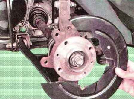
Remove the brake shield
Unscrew the front wheel hub nut
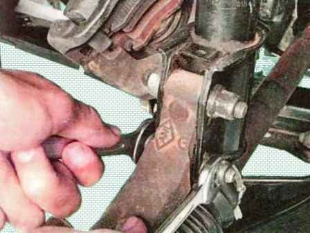
We unscrew the nuts of the bolts securing the steering knuckle to the shock strut and remove the bolts
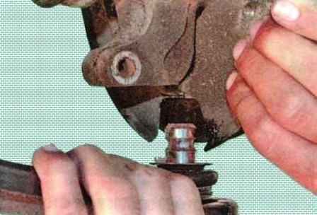
Remove the ball joint pin from the steering knuckle
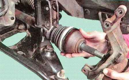
We push out of the hub in the direction of the gearbox, as far as possible, the splined shank of the outer CV joint of the front wheel drive
When doing this, make sure that the drive shaft does not come out of the side gear, as the hinge rollers can fall into the gearbox housing
Holding the drive shaft from a sharp lowering, remove the steering knuckle assembly with the hub
Hanging the drive shaft on a wire
Install all parts in reverse order.
Replacing the front wheel bearing
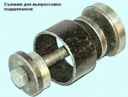
You will need a bearing puller, snap ring puller, barb, hammer
Remove the steering knuckle as described above
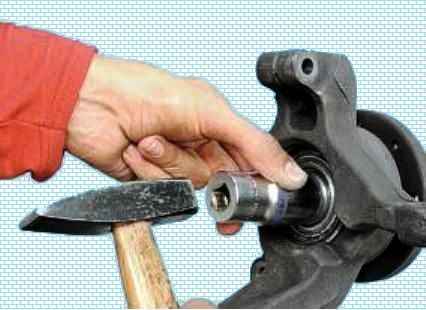
Clamp the steering knuckle in a vise and knock out the hub with a hammer using a suitable mandrel
Remove the hub. The outer half of the bearing inner ring usually remains on the hub.
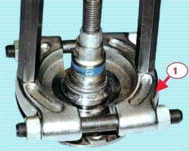
We install the puller and press out the outer half of the inner ring of the hub bearing.
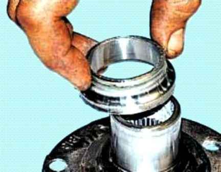
We install the bearing puller and press the outer race of the bearing out of the knuckle.
If there is no puller, we knock out the bearing using a mandrel of a suitable diameter.
We clean the parts and lubricate the inner surface of the fist socket and the outer surface of the hub with a thin layer of Litol-24.
We press the new bearing all the way into the steering knuckle (we apply the pressing force to the outer ring of the bearing)
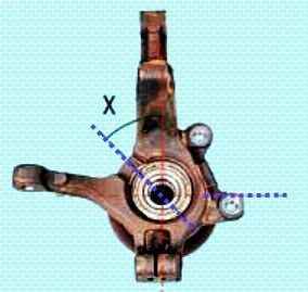
On vehicles with ABS, install the wheel speed sensor bracket so that the “X” angle is 35˚±5˚
Install the parts in reverse order.
Regular We check and, if necessary, adjust the angles of the wheels.


