Disassembling the carburetor to clean and replace worn parts
We remove the carburetor, as described in the article "How to remove and install the carburetor of a UAZ-3151, -31512, -31514, -31519"
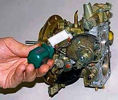
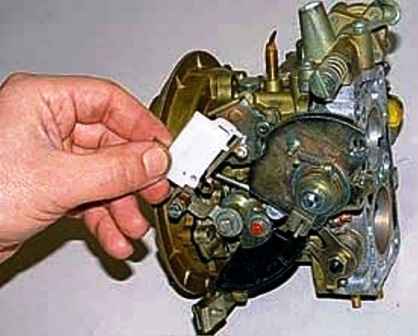
We unscrew the two screws securing the microswitch and remove it from the carburetor
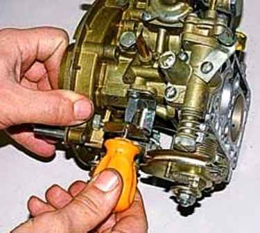
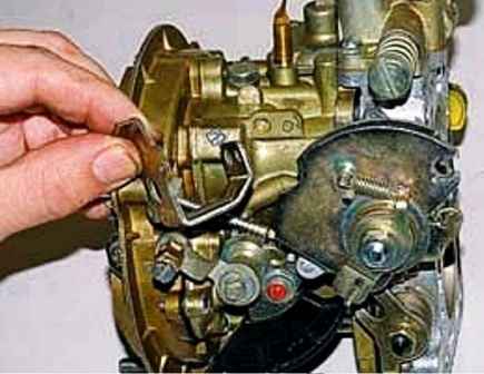
We unscrew the screw that secures the microswitch bracket with a screwdriver and remove the bracket
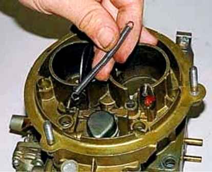
Remove the air damper closing spring
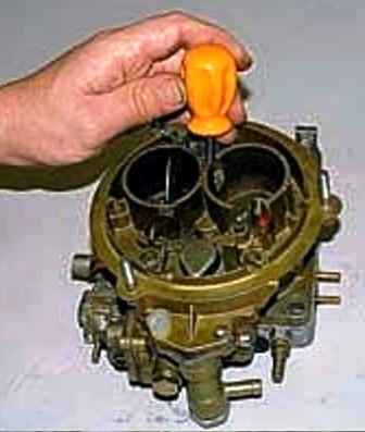
We unscrew the seven screws and lift the carburetor cover
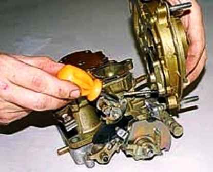
Removing the lower end of the air damper drive rod from the hole of the overhead lever of the trigger control cam, remove the carburetor cover
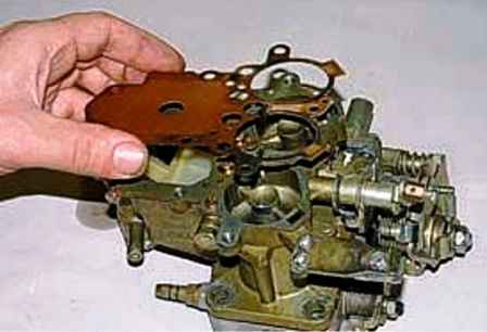
Remove the cardboard pad
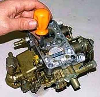
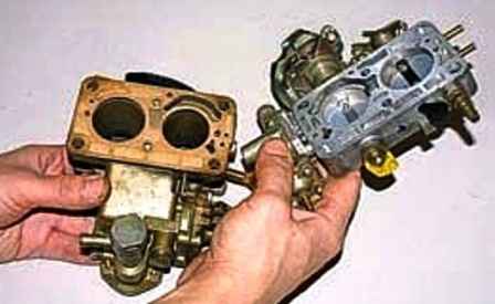
We unscrew the two screws and remove the throttle body
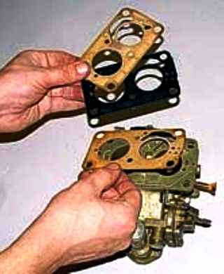
Removing three spacers
Disassembly of the carburettor cap
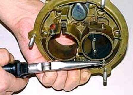
Using pliers, remove the cotter pin from the upper end of the air damper drive rod, remove the washer and remove the rod from the lever hole
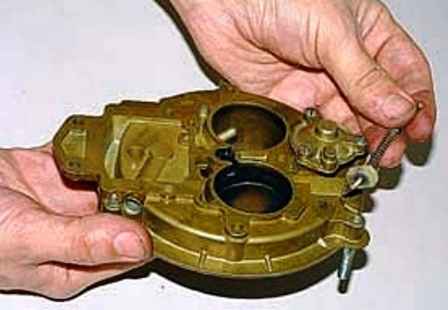
Remove traction
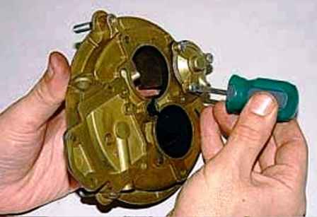
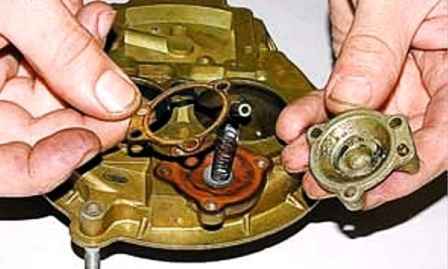
We unscrew the three screws and remove the cover of the pneumatic corrector with a cardboard gasket and a spring
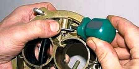
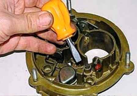
We disengage and remove the rod with the pneumatic corrector membrane
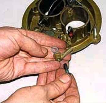
We unscrew the screw and remove the econostat atomizer. An o-ring is installed under the atomizer
We replace the defective membrane
We wash the metal parts in a solvent, blow with compressed air and assemble the carburetor cover
Disassembly of the carburetor body
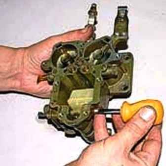
Unscrew the plug screw
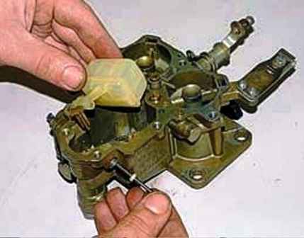
Remove the float axle with washer, float and valve needle from the body
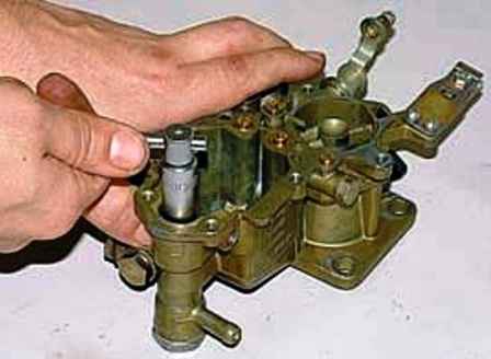
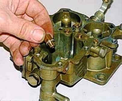
With a 10 head, unscrew the needle valve seat and remove it together with the O-ring
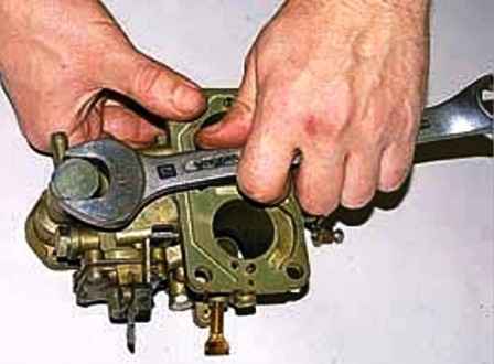
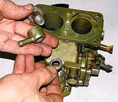
Using a 22 wrench, unscrew the fitting bolt and remove the fitting, two o-rings and the strainer from it
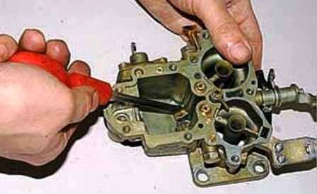
We unscrew the two fuel jets in the float chamber with a screwdriver
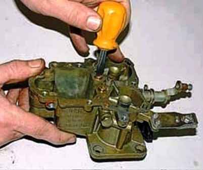
Turn off the air jets of both chambers
We mark the emulsion tubes so as not to be confused (the emulsion tube of the first chamber is longer, or it has more holes)
Turn the carburetor over and, tapping on it with a screwdriver handle, take out the emulsion tubes
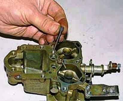
If the tubes do not fall out of the channels, take them out by screwing an M4 tap or a suitable self-tapping screw into them a few turns
We unscrew and remove the block of fuel and air idle jets with an emulsion tube
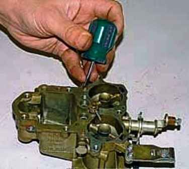
Unscrew with a screwdriver and take out the idle air jet
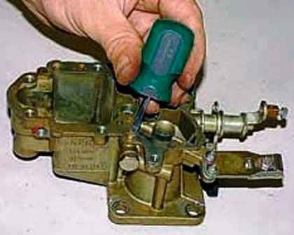
We also unscrew the air jet of the transition system of the second chamber, located symmetrically on the opposite side of the body
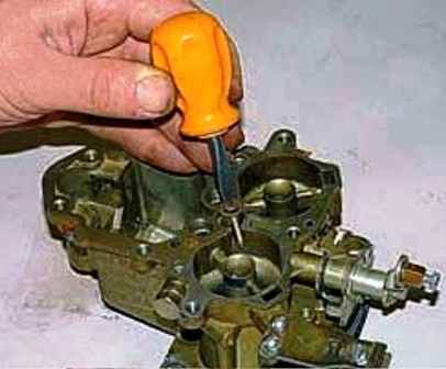
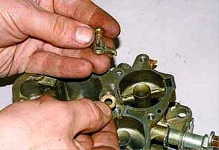
Unscrew the discharge valve and remove the accelerator pump spray with a sealing ring
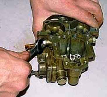
Using a 12 wrench, unscrew the cork
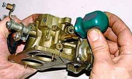
Using a screwdriver in the recess, unscrew the emulsion jet of the idle system
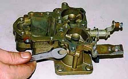
We also unscrew the emulsion jet of the transition system of the second chamber on the opposite side of the carburetor
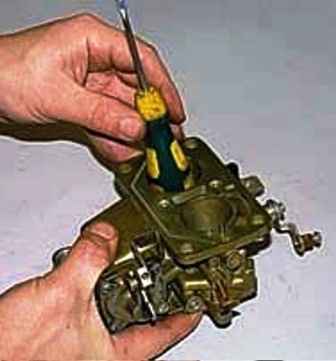
By tapping the small diffuser with a plastic screwdriver handle, we knock it out of the carburetor body along with the spring and gasket
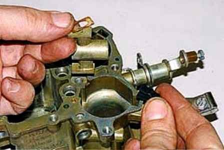
Also extract the diffuser of another chamber
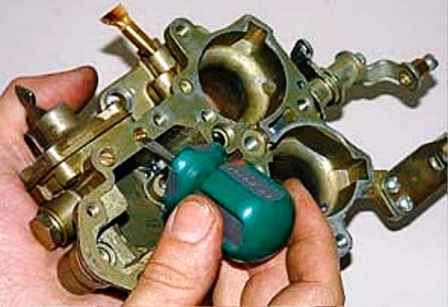
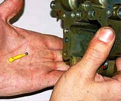
We unscrew the screw with a screwdriver and remove the valve ball stroke limiter together with the ball from the channel of the accelerator pump
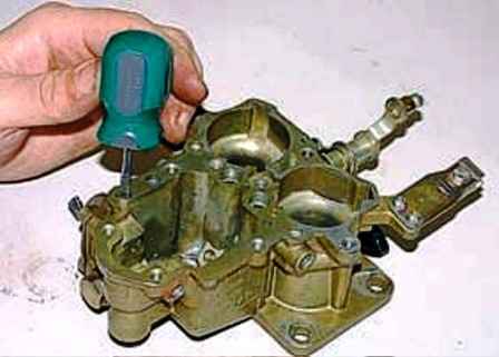
Turn the accelerator pump adjusting screw all the way, counting the number of revolutions
When reassembling, this will restore the factory setting
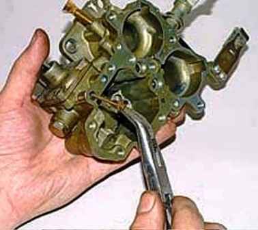
Unscrew and remove the adjusting screw with a sealing rubber ring
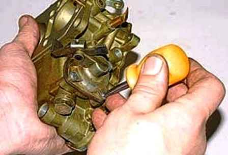
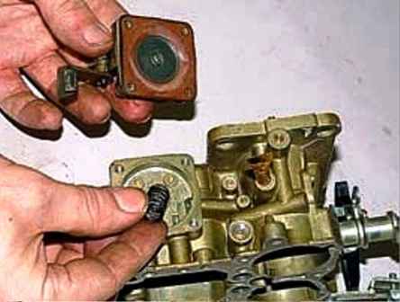
We unscrew the four screws and remove the cover of the accelerator pump with a membrane and a spring
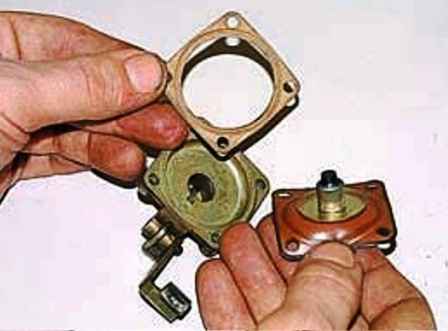
There is a cardboard gasket between the membrane and the lid.
We wash the metal parts in a solvent, blow with compressed air and assemble the carburetor body.
We replace the defective membrane.
We install small diffusers so that their side holes are aligned with the body channels and their connections are sealed with gaskets.
Throttle body disassembly
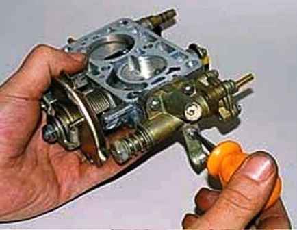
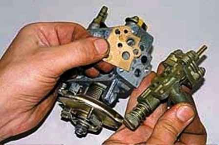
We unscrew the three screws and remove the forced idle economizer housing with gasket
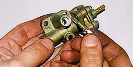
Unscrew the screw for adjusting the composition of the mixture (to qualities)
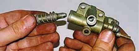
Unscrew the quantity screw
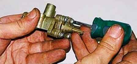
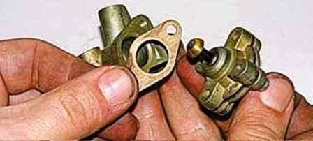
We unscrew the two screws and remove the forced idle economizer valve from the body
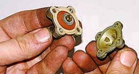
We unscrew the other two screws and remove the cover with the gasket
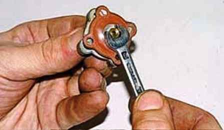
Unscrew the nut with a 6 key and remove the membrane from the stem and remove the stem from the body

The metal parts of the carburetor are well washed from deposits with acetone, but solvents for nitro paints No. 646, 647, 649, 650 or toluene can be used.
Solvents must not come into contact with plastic or rubber parts.
Before assembling the body parts, we blow compressed air and blow through the channels.
After assembling the carburetor, we check the fuel level in the float chamber (see "Maintenance and adjustment of the UAZ-3151, -31512, -31514, -31519 carburetor")
This adjustment can be made without installing a carburetor on the car.
To do this, you need to install the carburetor without a body cover on a horizontal plane.
We put on a rubber petrol-resistant hose on the fuel fitting of the carburetor, in which we create a slight excess fuel pressure with any improvised means, for example, with a syringe.
You can simply raise the end of the hose to a height of 30–40 cm and pour fuel into it through a funnel.
This pressure will be enough to fill the float chamber and take measurements.


