We remove the elements of the ignition system for repair and replacement
We discussed the replacement of the switch and emergency vibrator in previous articles
Removing and installing the ignition coil
Disconnect the negative battery terminal
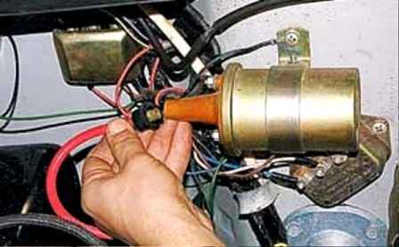
Disconnect the high-voltage wire from the coil
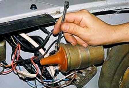
Using an 8 wrench, unscrew the two nuts and, having written down the order of connecting the wires, remove their tips from the ignition coil leads
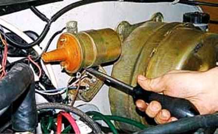
With a Phillips screwdriver, completely unscrew the bottom screw and unscrew the top screw securing the coil a few turns
The top screw still secures the ground wire lug
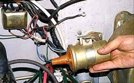
Remove the coil
Install the new coil in reverse order
Removing and installing additional resistance
Disconnect the negative battery terminal
We mark the order of connecting wires to the additional resistance
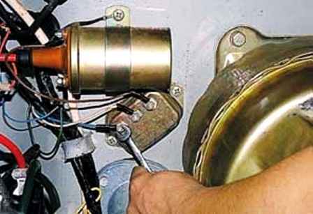
Unscrew the nut that secures the blue-insulated wire tip to the “+” terminal and disconnect it from the additional resistance
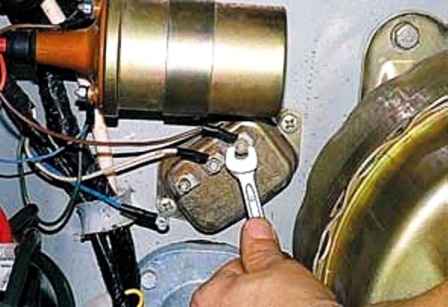
Using an 8 wrench, unscrew the nuts securing the tips of the two wires to the additional resistance and disconnect them
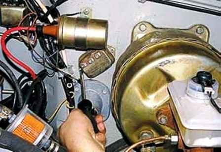
Using a Phillips screwdriver, unscrew the two screws securing the additional resistance to the body and remove the resistance
Set the new resistance in reverse order
Replacing the ignition lock and ignition relay
Disconnect the negative battery terminal
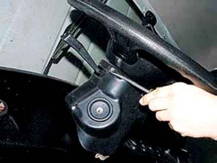
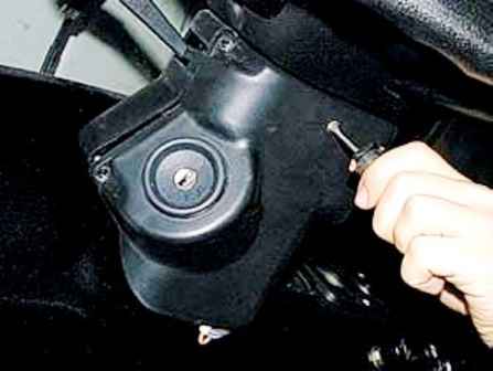
With a flat screwdriver, unscrew the four screws connecting the steering column covers
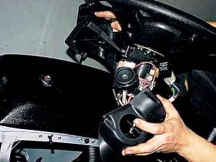
Use a Phillips screwdriver to unscrew the screw securing the lower part of the casing and remove the casing
In its lower part there is a block of wires with a connected ignition relay
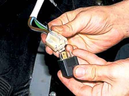
To replace the relay, disconnect it from the wiring block and install a new one
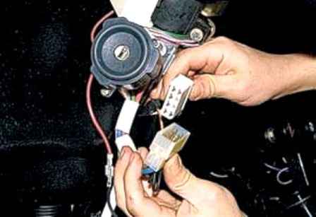
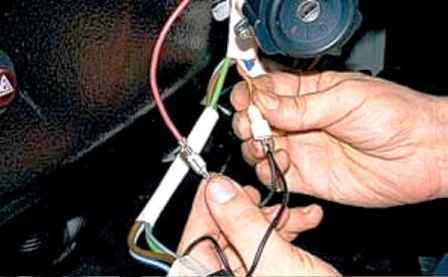
To remove the ignition switch, disconnect the ignition switch wire block switch and two ignition relay connectors
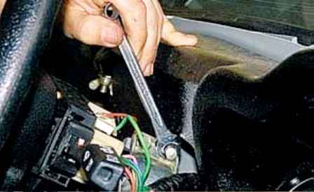
Using a 10 key, we unscrew the two special (with breaking off heads) bolts securing the switch to the steering column
If the bolt heads are broken, you can unscrew the bolts with a chisel
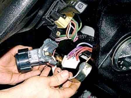
Remove the switch from the steering column
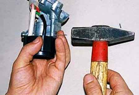
With a thin beard we knock out two locking pins
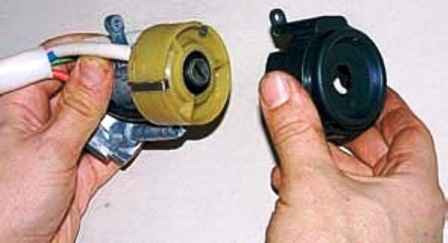
Use a Phillips screwdriver to unscrew the screw securing the lining and remove it
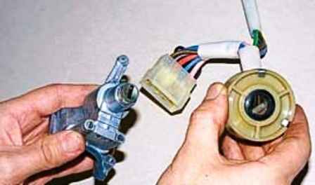
Remove the contact group
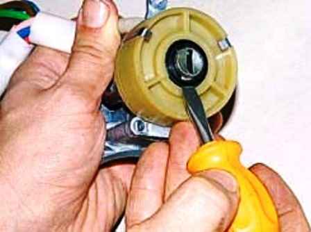
We install a new contact group so that the protrusion on the lock cylinder enters the groove of the contact group
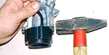
Put the pins into the holes with a hammer
Further assembly is carried out in the reverse order


