
The ignition system is non-contact.
It consists of a distribution sensor, a switch, an ignition coil, spark plugs, additional resistance, an emergency vibrator, high and low voltage wires
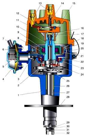
Sensor-distributor of ignition: 1 - housing; 2 - centrifugal regulator weight; 3 - bearing fastening screw; 4 - vacuum regulator; 5 - vacuum regulator spring; 6 - diaphragm; 7 - fitting; 8 - magnetic circuit of the rotor; 9 - permanent magnet of the rotor; 10 - rotor; 11 - cover; 12 - noise suppression resistor; 13 - conclusions; 14 - central contact; 15 - slider; 16 - felt; 17 - rotor fastening screw; 18 - stator winding; 19 - stator mounting screw; 20 - stator; 21 - magnetic circuit of the stator winding; 22 - stator support; 23 - bearing; 24 - weight spring; 25 - thrust washers; 26 - bushing; 27 - roller; 28 - octane corrector plate; 29 - washer; 30 - spring ring; 31 - pin; 32 - drive clutch
Ignition distributor (type 3706) - non-contact, with a control pulse generator and built-in vacuum and centrifugal ignition timing controllers.
The distributor sensor performs two functions: it sets the sparking moment depending on the crankshaft speed, engine load, and distributes high voltage pulses to the spark plugs in accordance with the firing order of the cylinders.
For this purpose, a slider mounted on the shaft of the distribution sensor is used.
The slider contains an interference suppression resistor.
The switch (13.3734) opens the power circuit of the primary winding of the ignition coil, converting the control pulses of the sensor into current pulses in the ignition coil (B116).
Technical characteristics of the ignition system
Cylinder order 1-2-4-3
The direction against the rotation of the rotor of the clock sensor-distributor arrows
Ignition advance angle, deg:
- centrifugal governor 15–18
- Vacuum regulator 8-10
A11 or A14M spark plugs
Spark gap between spark plug electrodes, mm 0.85–1.0
Slider resistance, kOhm 5–8
Tip resistance, kOhm 4–7
Resistance of the central contact of the cover*, kOhm 8–13
Stator winding resistance, kOhm 0.4-0.45
* A carbon contact is installed on the part of the distribution sensors instead of a resistor.
The ignition coil is a high voltage transformer.
Primary is low voltage, secondary is high.
The windings are placed in a sealed metal case filled with oil.
The emergency vibrator allows you to get to the place of repair with a faulty switch or a damaged stator winding of the ignition distributor sensor.
To turn on the emergency vibrator, we connect the tip of the wire connected to the "short circuit" output of the switch to the contact output of the vibrator.
Setting the ignition system to work in emergency mode
To switch the ignition system to work with an emergency vibrator, turn off the ignition

Under the instrument panel on the right side, use a flat screwdriver to unscrew the screw that secures the wire end to the "short circuit" terminal of the switch

Attach the end of the wire to the output of the vibrator and fasten it with a screw

In the engine compartment, remove the hose from the forced idle economizer valve

Remove the hose from the central fitting of the electromagnetic valve of the EPHX system

Put on this shlang to economizer valve fitting
Now the ignition system will work in emergency mode
Emergency vibrator life is limited to 30 hours
Therefore, as soon as possible, it is necessary to eliminate the malfunction of the ignition system: replace the switch or the stator of the distribution sensor and put the system into operation.
To do this, we connect the wire to the "short circuit" terminal of the switch and return the hoses of the EPHX system to their original places
After a long operation of the ignition system on the emergency vibrator, it is necessary to replace the vibrator with a new one
To replace the switch:
Disconnect the negative battery terminal
We mark the order of connecting wires to the switch outputs

We unscrew the three screws securing the wire lugs to the switch terminals with a screwdriver and disconnect the wires

Use a Phillips screwdriver to unscrew the two mounting screws and remove the switch

Install the switch in reverse order
Replacing the emergency vibrator
If the vibrator was included in the ignition system, turn it off


Using a Phillips screwdriver, unscrew the two screws securing the vibrator to the body and replace the emergency vibrator

")
")
")
")
")
")
")
")