
The system consists of an electronic control unit, a microswitch, a forced idle economizer valve, a solenoid valve, connecting hoses and wires (Fig. 1)
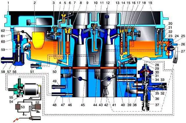
Carburetor diagram: 1 - cover. 2 - float; 3 - air jet of the transition system of the second chamber: 4 - fuel jet of the transition system of the second chamber: 5 - threaded screw-holder of the econostat atomizer: 6 - main air jet of the second chamber; 7 - econostat atomizer: 8 - emulsion tube of the main dosing system of the second chamber: 9 - small diffuser of the second chamber with atomizer: 10 - discharge valve; 11* - accelerator pump atomizer: 12 - air damper; 13 - small diffuser of the first chamber with atomizer: 14 - main air jet of the first chamber: 15 - emulsion tube of the main dosing system of the first chamber; 16 - block of fuel and air idling jets with an emulsion tube: 17 - emulsion jet of the idling system: 18 - idling air jet: 19 - adjusting needle on the jet of the drainage channel of the accelerator pump: 20 - stroke limiter of the ball valve of the accelerator pump; 21 - carburetor body. 22 - bypass (drainage) jet of the accelerator pump; 23 - accelerator pump valve ball: 24 - accelerating pump diaphragm spring: 25 - accelerating pump diaphragm; 26 - accelerating pump diaphragm cover; 27 - accelerator pump drive lever, 2S - main fuel jet of the first chamber, 29 - EPHX valve fitting; 30 - EPHX valve diaphragm; 31 - shut-off valve EPHKh; 32 - plastic limiter for turning the quality screw: 33 - screw for adjusting the composition of the mixture at idle (quality screw); 34 - unloading sub-diaphragm hole in the EPHX valve body, 35 - forced idle economizer body (idling unit): 36 - idle system valve seat: 37 - screw for adjusting the idle speed of the crankshaft; 38 - gasket, 39 - additional screw for adjusting the composition of the mixture on the main idling fuel supply branch (only on early modifications of carburetors); 40 - transitional slotted hole of the idle system, 41 - throttle valve of the first chamber, 42 - accelerator pump lever drive cam, 43 - accelerator pump lever roller, 44 - inlet window of the air channel of the idle system; 45 - throttle valve of the second chamber; 46 - thermal insulating gasket of the carburetor body, 47 - throttle body, 48 - vacuum extraction fitting to the EPHX solenoid control valve; 49 - vacuum extraction fitting to the vacuum ignition timing controller; 50 - main fuel jet of the second chamber; 51 - vacuum extraction fitting to the exhaust gas recirculation valve, 52 - power circuit of the EPHX control unit, 53 - microswitch circuit of the EPHX system; 54 - filter on the vent fitting of the EPHX solenoid control valve; 55 - solenoid valve of the EPHX system, 56 - fitting bolt, 57 - fuel filter, 58 - fuel supply fitting, 59 - plug on the wall of the float chamber; 60 - shut-off valve of the float mechanism; 61 - locking needle earring; 62 - float tongue • For carburetors installed on an engine with a displacement of 2.5 liters, the atomizer has one nozzle 1 directed into the first chamber.
The unit controls the operation of the solenoid valve depending on the speed of the crankshaft.
In idle mode, the control unit energizes the outputs of the solenoid valve, which opens and passes vacuum from the throttle space of the carburetor to the economizer. The economizer valve, in turn, opens the idle channel.
When the speed rises above 1600 min–1, the unit turns off the power to the solenoid valve winding.
At the same time, the space above the economizer diaphragm is connected to the atmosphere through the valve, the vacuum drops, and the economizer valve closes the idle channel under the action of the spring.
When the speed drops to 1300 min–1, the control unit re-energizes the solenoid valve.
The valve opens, passing vacuum to the economizer diaphragm and the economizer valve opens the idle channel.
The solenoid valve is de-energized when the ignition is turned off, thereby preventing self-ignition of the fuel-air mixture in the cylinders.
The microswitch is mounted on the carburettor.
When the throttle is opened, it supplies voltage to the solenoid valve, bypassing the control unit.
Checking and replacing the EPHX solenoid valve

Turn off the ignition and remove the wire ends from the solenoid valve terminals

Remove the hoses from the valve nozzles, marking their position

With a Phillips screwdriver, unscrew the screw securing the valve and the tip of the ground wire
We check the operation of the valve, for which we apply a voltage of 12 V (DC) to the valve terminals.
With the mouth we create pressure in its side pipe.
For a serviceable valve, air should exit through the second branch pipe, and when the voltage is removed, through the air filter of the valve.
We replace the defective valve.
When installing the valve, make sure that the hoses are connected to it correctly: the side pipe is connected to the economizer, and the central one is connected to the throttle space of the carburetor.
Connect the wire ends to the valve terminals in random order.
Checking and replacing the control unit
It is recommended to check the EPHX control unit with a car tester with a tachometer function

Disconnect the wires from the carburetor microswitch

Remove the insulating tubes from the wire ends
Connect the voltmeter clamps to the terminals of the solenoid valve
Instead of a voltmeter, you can use a test lamp
Connect the tester (tachometer) to the engine and start the engine

The voltmeter should show the presence of voltage
Increase the engine speed.
When the frequency reaches 1600 min–1, the unit should turn off the power supply to the valve, and after the speed drops to 1200 min–1, turn it on again.
We replace a defective power supply.

With the ignition off, under the instrument panel, disconnect the wire block from the control unit

Use a Phillips screwdriver to unscrew the two screws securing the unit
Install the new block in reverse order
Adjusting the position of the microswitch
Disconnect the wire tip from the microswitch.
Connect an ohmmeter to its terminals.
When the "gas" pedal is released, the contacts of the microswitch should be open (the ohmmeter should show high resistance), when the pedal is lightly pressed, they should be closed (the resistance shown by the ohmmeter is close to zero).

To adjust with a screwdriver, loosen the two screws securing the microswitch

By moving the microswitch, we achieve its optimal position, after which we tighten the screws

")
")
")
")
")
")
")
")