
If the valve does not fit tightly on the seat, then gaps are formed in some areas of the valve and seat.
In this case, gases under pressure and at high speed pass into the formed gaps, so in this place the chamfers are subject to severe corrosion and the valve fits worse on the seat.
Combustion products accumulate on the surface of the valve chamfer, as a result of which the tightness of the connection is broken.
We replace the oil deflector caps in case of increased oil consumption and during the next repair of the cylinder heads.
Removing and grinding the valves
We remove the cylinder head, as described in the article - "Replacing the cylinder head gaskets of the 740 Kamaz diesel engine".
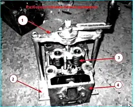
Install the cylinder head on a workbench or on the base of the I801.06.000 puller, if available.
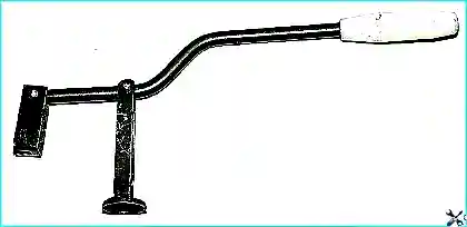
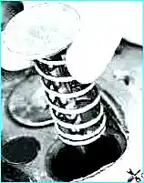
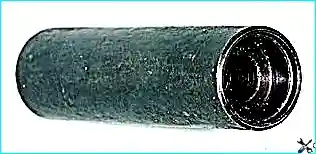
If there is no puller like the one in the picture (Fig. 1), you can use a puller for VAZ cars (Fig. 2)
Before compressing the springs, tap the spring plates with a hammer to make it easier to remove the locking crackers
Compress the valve springs until the crackers completely exit the bushing cone and remove the crackers
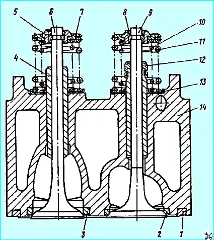
Remove bushing 5 (Fig. 3), plate 7, springs 10 and 11, washer 13, and take out the valves.
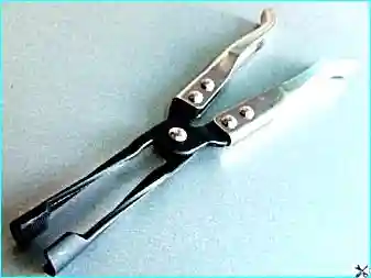
Using pliers (Fig. 4), remove the valve stem seals.
Clean the valves and valve seats from carbon deposits and we clean the remaining parts in diesel fuel.
The angles of the working chamfers should be within the limits of at the seat = 44˚45′; at the valve 45˚30′. These angles are set during restoration of the cylinder head and valve before grinding.
We put a pre-selected spring on the valve stem (Fig. 5) and insert the valve into the guide sleeve from the combustion chamber side, lubricating the valve stem with a layer of graphite grease.
Graphite grease prevents the abrasive from the lapping paste from getting into the guide bushing holes and facilitates the rotation of the valve during lapping.
Put the valve lapping device on the valve stem (or, with some tension, a rubber tube for connecting the valve to the reversible drill).
Apply a uniform thin layer of lapping paste to the working surface of the valve chamfer.
Turning the drill to the minimum rotation speed (in reverse mode) or rotating the device (in the case of manual lapping) alternately in both directions by half a turn, lap the valve, periodically pressing it against the seat, then weakening the pressing force.
Continue lapping until a uniform matte belt with a width of not less than 1.5 mm.
We wash the valve seats and valves in diesel fuel, blow them with compressed air and check the quality of the lapping
To check the quality of the lapping, we apply six to eight lines across the valve chamfer at an equal distance with a soft pencil, insert the valve into the seat and, pressing hard, turn it a quarter of a turn. If all the lines are erased, then the valve is well lapped
Assembling the cylinder head
We insert the valves into the guide bushings, lubricating them with engine oil. Install washers 13 (Fig. 3).
Using the device (Fig. 6), press in the valve stem seals.
Install the springs, spring plates and, having compressed the springs, insert the locking crackers.
After installing the crackers and removing the device for compressing the valve springs, apply several light blows with a hammer to the end of the valve stem to ensure that the crackers are fixed in the groove of the stem.
If the crackers installed at an angle remain unfixed, when the engine is started, the "uncracked" valve will fall into the cylinder, which will lead to a serious engine failure.
Check the tightness of the valves. We place the head with the combustion chambers facing up and pour a little kerosene up to the rim into the combustion chamber
If the kerosene does not leak into the head channel within 3 minutes, the valve is sealed.
If kerosene leaks, lightly tap the end of the valve with a rubber hammer. If the leak does not stop, we grind the valves again.

")
")
")
")
")
")
")
")