In the article, we will consider the removal, inspection and installation of elements of the engine fuel system.
Injection pump replacement
Disconnect the negative battery terminal
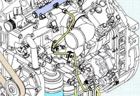
Disconnect the inlet and outlet pipes from the injection pump
Disconnect the fuel supply line going to the rail from the injection pump and loosen the support brackets.
Disconnect the fuel control valve harness connector
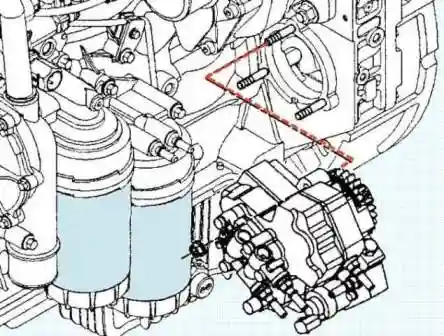
We unscrew the three bolts of the high pressure fuel pump
Remove the fuel pump from the timing gear housing
Disassembly
Disassembly, involves only the replacement of the pump drive.
Use the fuel pump gear changer (#4919109) and a 1/2" pry bar to hold the injection pump drive gear in place.
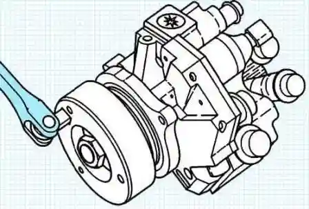
Loosen the fuel pump drive gear nut by turning it counterclockwise.
Do not remove it from the shaft
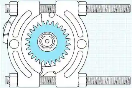
Install the Snap-On TM Bearing Remover (#CJ951) between the fuel pump mounting flange and the drive gear.
Lock the bearing remover.
Install Snap-On TM (#CG150) to Snap-On TM Bearing Remover (#CJ951) and fuel pump drive shaft.
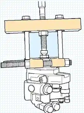
Turn the puller screw to separate the gear from the drive shaft.
Remove the fuel pump drive gear nut, lock washer and gear from the fuel pump drive shaft.
Assembly
Before assembling, clean and dry the nose of the drive shaft and the seat of the drive gear.
Wipe the drive shaft and gear with a lint-free cloth dampened with solvent.
Do not touch the seating surfaces after wiping.
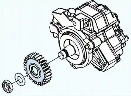
Install the drive gear onto the drive shaft, the lock washer and tighten the gear nut by hand.

While holding the gear from turning with a puller, tighten the gear nut. Tightening torque 105 Nm
Installation
Note: synchronization of the fuel pump with the crankshaft is not required.
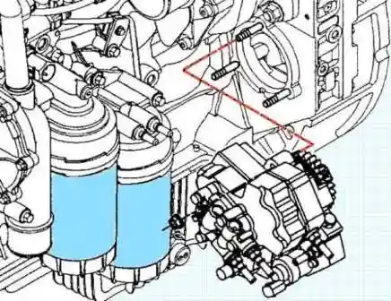
Mount the fuel pump to the timing gear housing.
Tighten the fuel pump mounting bolts. Tightening torque 25 Nm
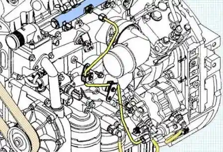
Install the high pressure fuel pipe from the injection pump to the fuel rail, tighten the holders.
Note: Hold the injection pump outlet fitting with a second wrench to prevent over-tightening. Tightening torque 21± 4 Nm
Connect the feed control valve harness connector.
Install the fuel lines.
Install the drain pipes.
Connect the wires to the battery terminals.
Fill the system with fuel m.
Checking and replacing the fuel control valve
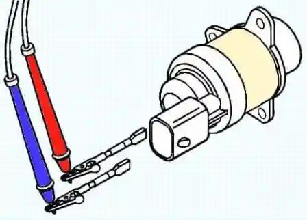
Measure the resistance of the fuel control valve.
Maximum resistance should be 5 ohms
Removing the valve
Disconnecting the connector
Unscrew the three bolts
Remove the flow control valve by turning and pulling it outward
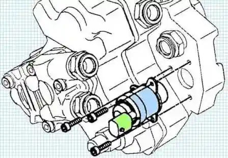
Installation
Install a new O-ring on the fuel control valve. Lubricate the new O-ring with clean oil
Install the fuel control valve by turning it and inserting it inward flush with the seating surface of the injection pump.
Tightening torque:
- - first stage 3 Nm;
- - second stage 7 Nm.
Connecting the connector.
Injectors
Checking fuel drain
Note: Bad injectors will cause excessive fuel leakage through the return line.
For engines with a fuel rail relief valve quick coupler, use an appropriate drain hose and plug to block fuel flow through the pressure relief valve.
Disconnect the quick connector from the pressure reducing valve.
Connect the gauge adapter (#4918462) to the fuel accumulator pressure relief valve and drain the fuel into a container.
Install the quick plug (#4918464) on the fuel return hose to prevent fuel from entering the fuel return line.
Start the engine. Turn on the “Fuel Leakade Test” mode on the “INSITE” diagnostic complex and let the operating temperature rise for 1 minute.
At higher temperatures, greater measurement accuracy is achieved.
Place the drain hose (#4918462) in a measuring container and measure the amount of fuel drained in 1 minute.
The “Fuel Leakade Test” mode of the “INSITE” diagnostic complex is on, less than 200 ml/minute
Idling (may not leak) less than 120 ml/minute
Engine cranking less than 90ml/minute
If fuel leakage is greater than the maximum value, it is necessary to block the return of fuel on one of the injectors in order to localize the cause of excessive leakage.
With the engine off, remove the first cylinder high pressure fuel pipe.
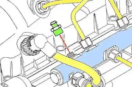
Install the plug (#4918860) on the fuel accumulator fitting where the first injector high pressure fuel pipe attaches. Tightening torque 30 Nm
Retest for leaks and record the result
Install the high pressure fuel pipe
Repeat the leak test one by one, turning off the remaining injectors.
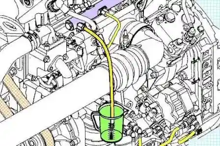
Identify which injector is leaking (leakage is minimal with the failed injector blocked).
If the leaks are approximately equal, then several injectors may be damaged.
Withdrawal
Disconnect the connectors from the injectors.
Disconnect the high pressure fuel lines from the injectors and from the fuel rail.
Note: clean all connections before disassembly. The ingress of dirt or debris can cause damage to the fuel system.
Remove the nut and disconnect the #4 high pressure fuel pipe from the fuel accumulator.
Remove the nut and disconnect the #4 high pressure fuel pipe from the #4 injector.
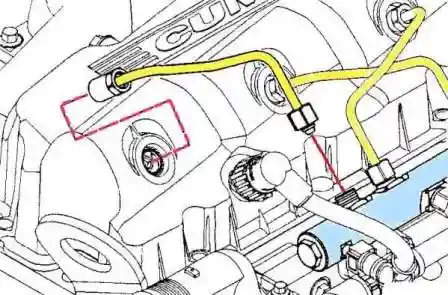
Repeat the procedure for the remaining injectors. Close all open ports with covers.
Remove the cylinder head cover.
Remove the injector drain pipe.
Note: Mark all fuel drain line retainers and gaskets so that they can be reinstalled in their original locations when reassembling.
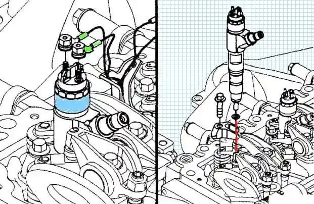
Remove the nozzles.
Unscrew the nuts securing the injector wiring, remove the wires.
Loosen and remove the nozzle holder bolt. c) to remove the nozzle, you can use a pry bar with a small heel.
Lift the injector by the clamping flange (the part of the injector body that is slightly above the cylinder head casting).
Remove the nozzle holder.
Remove the injector from the cylinder head.
Check
Clean the nozzle in an ultrasonic bath with an aqueous solution.
Check the condition of the injector parts for damage.
Put the protective cap on the nozzle.
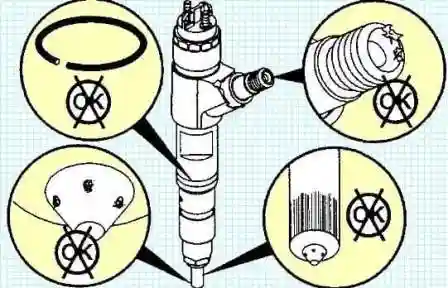
Note: As a result of overheating, the atomizer turns brown-yellow or blue, which leads to damage to the nozzle, depending on the degree of overheating.
Check the resistance at the injector terminals.
Rated resistance less than 3 ohms
Installation
Check the thickness of the new copper sealing washer.
Nominal thickness 2.5 mm
Do not install two copper washers!
Remove the dirt around the nozzle bore.
Lubricate the injector O-ring with engine oil.
If the nozzle is good, install it in the place where it was removed from.
Install the holder on the nozzle before installing the nozzle in the bore.
Orient the injector correctly in the cylinder head (fuel fitting towards the high pressure fuel pipe connector).
Use the shipping cap on the top of the nozzle to make sure it fits correctly.
Tighten the nozzle holder bolt.
Install the other 3 nozzles.
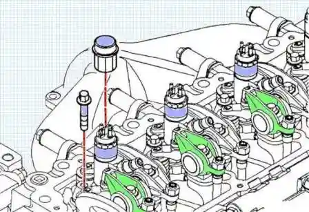
Install the cylinder head cover without seals
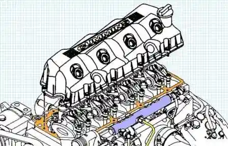
Tighten one screw on each side of the cover.
Connect the high pressure fuel pipe to the injector.
Using the tube nut as a guide, center the nozzle in the seal.
Remove the high pressure fuel pipe from the injector and repeat for the remaining injectors.
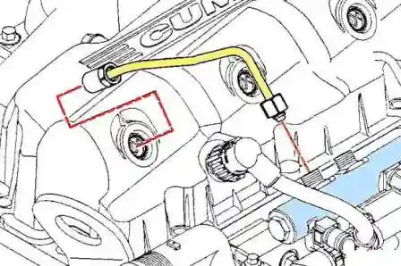
Remove the cylinder head cover.
Tighten the nozzle holder bolts evenly in several passes.
Note: Tighten the bolts alternately by turning 90° until the rated torque is reached. Tightening torque 33 Nm
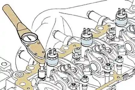
Connect the injector wires and tighten the nuts.
Tighten the nuts.
Note: route the injector wires so that they do not come into contact with each other or with the rocker arms.
If the rocker comes into contact with the injector wiring, the insulation of the wiring will be damaged, causing diagnostic codes to occur. Tightening torque 1.5 Nm
Install the cylinder head cover.
Connect the high pressure fuel lines.
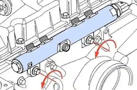
Loosen the fuel rail mounting bolts. Do not remove the fuel rail!
The bolts are loosened to ensure proper orientation of the fuel rail after installing the high pressure fuel lines.
Install and hand-tighten the high pressure fuel line nuts.
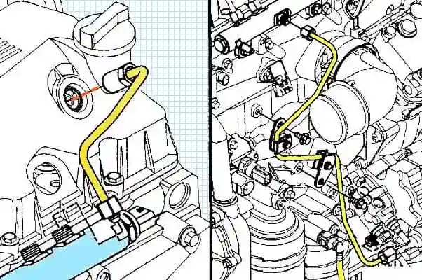
Tighten the nuts securing the fuel high pressure pipes. Tightening torque 22 Nm
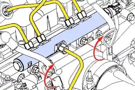
Tighten the fuel rail mounting bolts. Tightening torque 24 Nm
Connect the wires to the battery.
Start the engine and check for leaks.
Removing and installing the fuel rail
Disconnect the negative battery terminal
Remove the high pressure fuel pipes.
Remove the nut and disconnect the #4 high pressure fuel pipe from the fuel accumulator.
Remove the nut and disconnect the #4 high pressure fuel pipe from the #4 injector.
Repeat the procedure for the remaining injectors. Close all open ports with covers.
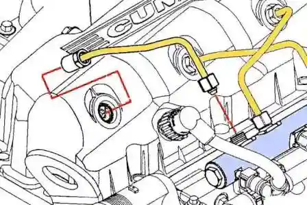
Disconnect the fuel pressure sensor connector. Note: do not remove the fuel pressure sensor, as if removed, it will need to be replaced.
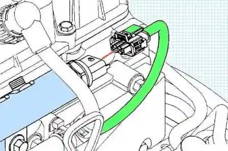
Remove the fuel drain line from the fuel pressure relief valve.
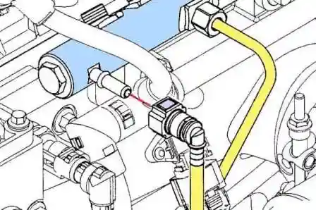
Disconnect the high pressure fuel pipe connecting the injection pump and the fuel rail from the fuel rail.
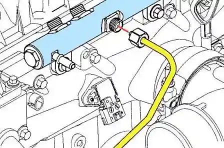
Remove the fuel rail mounting bolts.
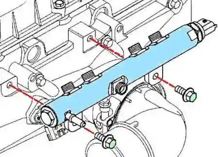
Remove the fuel rail.
Installation
Install the fuel rail.
Mount the fuel rail to the engine.
Tighten the fuel rail mounting bolts by hand.
Connect the high pressure fuel pipe from the injection pump to the fuel accumulator.
Note: Keep the fitting from turning. Tightening torque 30 Nm
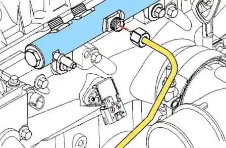
Install the high pressure fuel pipes on the injectors and fuel rail.
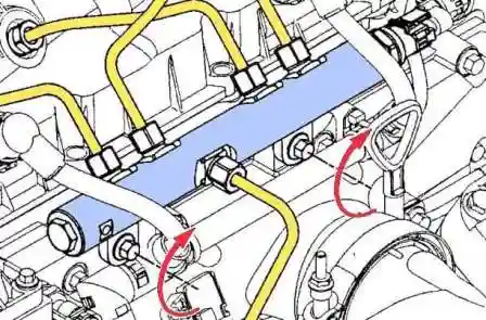
Tighten the fuel rail mounting bolts. Tightening torque 24 Nm
Connect the fuel pressure sensor connector.
If removed, install the fuel pressure sensor. Tightening torque 70 Nm
Connect the fuel drain line to the fuel pressure relief valve.
If removed, install pressure reducing valve. Tightening torque 100 Nm
Connect the wires to the battery.
Start the engine and check for leaks.
Reducing valve
Check
Remove the quick connector from the pressure reducing valve and install the pressure gauge adapter (#4918462) instead.
Install the quick-release shut-off connector (#4918464) on the drain line that is disconnected from the pressure reducing valve.
Place the end of the drain hose into a measuring container.
Turn on the fuel system pressure check in the “INSITE ТМ” diagnostic complex or let the engine idle.
Place the other end of the drain hose or pressure gauge adapter into a container and measure the flow.
Technical requirements for idling: No flow
When you turn on the test of the diagnostic complex “INSITE tm" : The maximum fuel consumption is 16 ml per minute.
Note:
- If too much fuel flows out of the pressure reducing valve, restart the engine and set the idle speed to high.
The engine management system will try to eliminate the problem due to the valve blemu.
- If fault codes 449, 1911, 2311, 272, 553 or 2216 appear, do not replace the pressure reducing valve until the cause of the failure is determined.
Removal and installation
Unscrew the pressure reducing valve.
Clean contact surfaces from dirt.
Close the pressure reducing valve. Tightening torque 100 Nm
Fuel filter
Removal and installation
Disconnect the connector from the water sensor.
Loosen and remove the fuel filter.
Make sure the O-ring is not stuck to the fuel filter head.
Remove the O-ring if necessary.
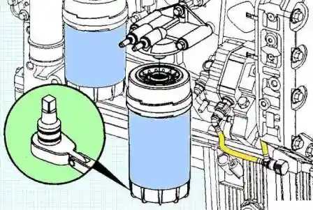
Lubricate the O-ring with clean oil.
Install the fuel filter on the filter cap.
Turn the filter in until it contacts the cap.
Use a puller to tighten the filter 3/4 turn. Tightening torque 23 Nm
Note: Do not prefill the fuel filter with fuel.
Bleed the low pressure fuel system with a hand pump (140 - 150 strokes for a dry filter).
Start the engine.
If the engine does not start within 30 seconds, turn off the ignition.
Operate the priming pump again, repeating the above steps until the engine starts.
If the engine starts, it may run erratically and noisily for the first few minutes, which is not a malfunction.


