
KAMA3-740.50-360, KAMA3-740.51-320 engines, designed for installation on single vehicles and truck tractors used as part of road trains, supplied to the domestic market and to countries with moderate and tropical climates, as well as supplied as spare parts.
Engines manufactured in the "U" version according to GOST 15150-69 are designed for operation at ambient temperatures from minus 45 to plus 40 °C, relative air humidity up to 75% at a temperature of 15 °C and in areas located at an altitude of up to 3000 m above sea level with a decrease in power, economic and other indicators up to 20%, with overcoming passes up to 4500 m.
Engines manufactured in the "T" version according to GOST 15150-69, designed for operation at ambient temperatures from minus 10 to plus 45 °C, relative air humidity up to 80% at a temperature of 27 °C and in areas located at an altitude of up to 3000 m above sea level with a decrease in power, economic and other indicators to 20%, with overcoming mountain passes up to 4500 m.
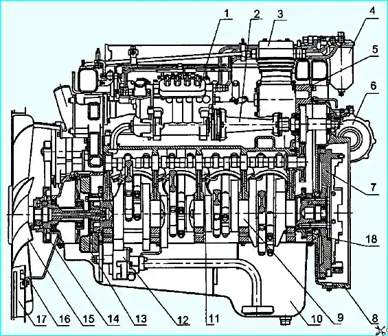
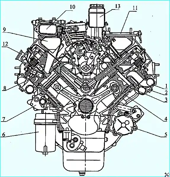
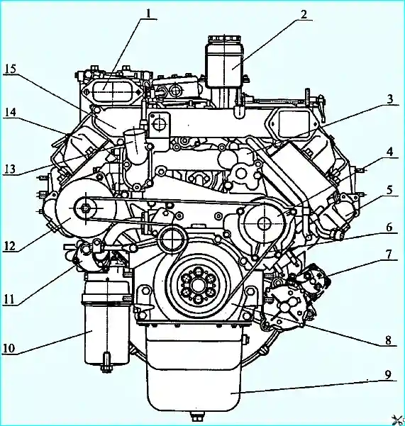
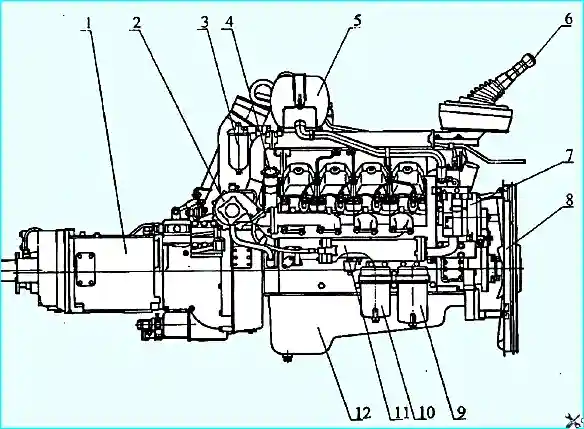
The general view, longitudinal and transverse sections of the engines are shown in Figures 1-5.
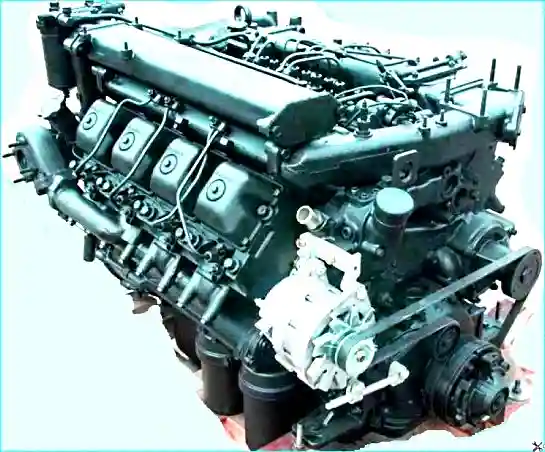
Four-stroke engines with compression ignition, liquid cooling, with a V-shaped arrangement of eight cylinders, with turbocharging and intermediate air cooling (IAC) of the "air-to-air" type.
In terms of emissions of harmful substances with exhaust gases, the 740.50-360 and 740.51-320 engines comply with the requirements of the UNECE regulations (EURO-2).
The basic part of the engines is the cylinder block, on which the units and parts of the engine are installed and secured.
Wet cylinder liners are installed in the bore of the half blocks.
The cylinder liners are closed from above by heads, separate for each cylinder. The cylinder block is closed at the bottom by a stamped oil sump.
The camshaft is located in the cylinder block on five plain bearings. The crankshaft is installed oval in the lower part of the block.
The engine cooling system is liquid, closed type, designed for the use of low-freezing coolant.
Technical characteristics of the engine 740.50-360, 740.51-320
Parameter name - Value
Engine type - Four-stroke, with compression ignition
Cylinder arrangement - V-shaped, with a 90° camber angle
Cylinder firing order - 1-5-4-2-6-3-7-8
Direction of crankshaft rotation - right (counterclockwise, when viewed from the flywheel side)
Cylinder diameter and piston stroke, mm: 120x130
Working volume, l: 11.76
Rated power, kW (hp): 265 (360); for engine 740.51-320: 235 (320)
Maximum torque, Nm (kgf m): 1470(150); for engine 740.51-320: 1275 (130)
Installation angle of fuel injection advance, degrees: 9+1
Compression ratio 16.8 (±2)
Crankshaft speed, min -1:
- - nominal 2200±50
- - at maximum torque 1300-1500
at idle:
- - minimum 600±20
- - maximum 2530-80
Number of valves in the cylinder head - 2 (inlet and exhaust)
Clearances on a cold engine, between the rocker arms and valve stems:
- - intake - 0.25...0.30 mm;
- - exhaust - 0.35...0.40 mm.
Oil pressure in a warm engine at crankshaft speed, kPa (kgf/cm²):
- - nominal 392...539 (4...5.5)
- - minimum idle, not less than 98 (1)
Injector, type - 273
Models 273.1112010-20 (273-20)
Nozzle manufactured by "YAZDA" models 273.1112010-20 or 273.1112010-50 (273-50)
Or models
Nozzle manufactured by BOSCH DLLA148S1380
Injector injection start pressure, MPa (kgf/cm²): 23.73...24.90 (242...254)
High-pressure fuel pump (HPFP) model 337-20.04; for engine 740.51-320: 337-20.03
Boost system - gas turbine with two turbochargers and air-to-air NVG.
Generator model G-273V or 6582.3701 (in accordance with the design documentation) - three-phase synchronous, alternating current, with a built-in rectifier unit
Generator G-273V:
- - rated current, A; 28
- - rated rectified voltage, V; 28
- - rated power, kW. 0.8
Generator mod. 6582.3701:
- - rated current, A; 75
- - rated rectified voltage, V: 28
- - rated power, kW. - 2.0
Starter 5662.3708 direct current, series excitation, with electromagnetic drive
- - rated power, kW 8.2
Gearbox model 161 mechanical, eight-speed;
- Or gearbox model ZF-16S151 of the company "ZAHNRADFABRIK" mechanical, sixteen-speed, includes a main four-speed box with a built-in two-stage divider located in front of the main box and with a two-stage planetary demultiplier located behind the main box.
Possible malfunctions and methods of elimination
Malfunction
- Cause of malfunction
Method troubleshooting
ENGINE
The engine does not start
- No fuel in the tank
Fill the fuel tank, bleed the fuel system.
- Air in the fuel system
Fix the leak, bleed the system.
- Incorrect fuel injection advance angle adjustment
Adjust the angle.
- Freezing of water that has gotten into the fuel lines or on the fuel tank intake screen
Carefully warm up the fuel filters, lines and tank with a rag soaked in hot water or steam, do not use an open flame for heating
The engine does not develop the required power, runs unsteadily, smoke during operation
- Clogged air cleaner or air intake cap
Carry out maintenance of the air cleaner or clean the cap mesh
- Insufficient fuel supply
Replace the fine fuel filter elements, flush the coarse filter, tighten the connections in the fuel pipes.
- Incorrect fuel injection advance angle adjustment
Adjust the angle.
- Clogged injector (coking of nozzle holes, stuck needle) or incorrect adjustment.
Flush the injector, replace the nozzle if necessary, check and adjust if necessary.
- Incorrect adjustment of the governor control lever drive (the control lever does not reach the maximum crankshaft speed limiting bolt).
Check and adjust the governor drive.
- Broken fuel injection pump pusher spring.
Replace the spring and adjust the pump on the stand.
- Hit dirt between the seat and the valve of the fuel pump or a broken spring.
Flush the valve or replace the spring, check the pump operation on the bench.
- Loss of tightness of the injection pump discharge valves or a broken spring.
Eliminate the leak in the valve workshop or replace the spring.
- Jamming of the plunger of the injection pump section
Replace the plunger pair and adjust the pump.
- Violation of the adjustment of thermal clearances in the valve timing mechanism.
Adjust the clearances.
- Depressurization of the membrane cavity or damage to the membrane of the corrector for boost air pressure.
Restore the tightness of the membrane cavity or replace the damaged membrane.
- Stoppage of oil supply to boost air pressure corrector.
Restore oil supply to the corrector.
- Loose fastening or breakage of the high-pressure tube.
Tighten the fastening nut or replace the tube.
- Poor compression due to piston group malfunctions or loose fit of the valve timing valves to the seats.
Check the condition of the pistons and piston rings, grind the valves.
- Thickening of the fuel (in cold weather).
Replace the fine fuel filter elements, replace the fuel with the appropriate season fuel, bleed the fuel system.
Low boost air pressure:
- air leakage through the connections of the intake manifold with the cylinder heads, pipes, turbochargers and compressor;
Tighten the connections, replace the gaskets and connecting hoses if necessary.
- gas breakthrough in the connections of the exhaust manifold and turbine housing;
Tighten the connections, replace the gaskets if necessary.
- turbocharger rotor seizure;
Replace the turbocharger.
- contamination of the exhaust tract, flow parts of the compressor and turbine.
Clean the pipelines, remove the turbocharger, and remove deposits from the flow parts.
Extraneous noise in the turbocharger
- Rotor rubbing against body parts
Tighten the bolts securing the turbine and compressor housings. Check for rotor rubbing at its extreme positions. If the rotor rubs, replace the turbocharger. If the noise persists, remove the turbocharger for maintenance.
High-frequency noise (whistle)
- The tightness of the engine intake and exhaust tracts is broken
Tighten the bolts and nuts securing the system components, replace the gaskets if necessary.
Increased oil consumption
- Long-term engine operation at idle speed.
Do not operate the engine at idle speed unless necessary.
- Oil leakage through the connections in the turbocharger lubrication system.
Tighten the connections, replace the gaskets and rubber sleeves if necessary.
- Wear of the valve-bushing mating in the cylinder head, aging of the rubber valve cuff.
Check and replace worn parts.
- Clogged air cleaner or air intake cap.
Service the air cleaner and clean the cap mesh.
Lower oil pressure in the lubrication system
- Low oil level in the oil pan.
Check and, if necessary, top up oil to the "B" mark.
- Malfunction of pressure control devices
Make sure that the devices are in good working order.
- Use of oil of the wrong viscosity
Change the oil to one that meets the chemotological chart.
- Contamination of the filter elements of the oil filter
Replace the filter elements.
- Maladjustment or jamming of the relief valve or lubrication system valve
Check the valves and eliminate jamming, adjust or replace faulty parts if necessary.
- Clogged oil pump intake
Flush the intake.
- Coolant entering the oil
Check the tightness of the water cavity, cylinder liner seal, tightness of the water-oil heat exchanger, replace faulty parts.
- Oil leaks at joints and oil lines of the lubrication system
Check the condition of process plugs, plugs, tightening of fasteners at joints, condition of sealing rings and gaskets.
- Malfunction of the oil pump
Remove the pump and check its operability on a special stand.
- Unacceptable increase in clearance in the crankshaft and camshaft bearings
Make repairs engine.
The oil temperature alarm comes on
- The oil temperature alarm sensor is faulty
Make sure the sensor is working properly, replace it if necessary.
- The heat exchanger switching thermostat is stuck, the thermal power sensor is faulty
Check the operation of the heat exchanger switching thermostat, replace it if necessary Eliminate jamming or replace the sensor.
- Clogged tubes or dirty cooling plates
Check the water-oil heat exchanger for clogged tubes and dirty cooling plates, flush or replace the heat exchanger if necessary.
Increased oil pressure in the lubrication system
- High oil viscosity.
Change the oil to the one corresponding to the chemotological chart.
- Loss of tightness of the control signal line connecting the main oil line to the pump or its clogging
Check the oil supply pipe to the pump, the tightening of the mounting bolts, the presence of a hole in the cover.
- Jamming or misadjustment of the lubrication system valve.
Check the valve and eliminate jamming, replace faulty parts if necessary.
Knocking during operation engine
- Early fuel injection into the cylinders.
Adjust the fuel injection advance angle.
- Increased thermal clearances in the valve timing mechanism
Adjust the clearances.
- Wedging of the valve timing mechanism valves in the bushings (the piston touches the valve)
Disassemble and clean the valve mechanism. Replace the valve if necessary.
- Increased cyclic fuel supply (the rack retainer has disengaged)
Replace the fuel injection pump rack
A dull knock from the crankshaft. Frequency increases with increasing crankshaft speed
- Unacceptable increase in clearance between journals and main bearing shells as a result of using oil that does not meet the specified specification or reducing oil pressure and supply.
Grind journals to the repair size and replace the shells, change the oil and check the operation of the oil pump.
- Unacceptable increase in clearance between the thrust half rings and the crankshaft.
Replace the thrust half rings with new ones of greater thickness.
- Loosening of the flywheel-to-crankshaft mounting bolts.
Establish the cause and tighten the bolts.
The knock of the connecting rod bearings is sharper than the knock of the main bearings
Can be heard when the engine is idling and increases with increasing speed crankshaft
- Unacceptable increase in the clearance between the journals and the liners of the connecting rod bearings as a result of using oil that does not meet the specified specification, or a decrease in oil pressure and supply.
Grind the journals to the repair size and replace the liners, change the oil and check the operation of the oil pump.
The pistons have a muffled knock, caused by the pistons beating against the cylinders
Can be heard at low crankshaft speed and under load
- Unacceptable increase in the clearance between the pistons and the cylinders.
Replace the pistons and, if necessary, the cylinder liners.
- Severe wear of the piston ring ends and the corresponding grooves on the piston.
Replace the piston rings and, if necessary, pistons.
Piston pin knock, double, metallic, sharp, caused by a large gap
Better heard when the engine is idling
- Unacceptable increase in the gap between the pin and the bushing of the upper head of the connecting rod.
Replace the pin and, if necessary, the connecting rod.
Increased fluid temperature in the cooling system*
- Weak tension or breakage of the water pump drive belts.
Tighten or replace the belts.
- Malfunction of thermostats
Replace thermostats.
- Contamination of the radiator core.
Clean the radiator core from dirt.
Increased coolant consumption
- Radiator damage
Repair the damage or replace the radiator
- Fluid leaking through the water pump mechanical seal.
Replace the mechanical seal.
- Coolant entering the lubrication system through the rubber sealing rings of the cylinder liners or through the rubber gaskets of the cylinder heads.
Replace the sealing rings of the cylinder liners or rubber gaskets.
* Before looking for the cause of the malfunction in the lubrication system and the cooling system, you need to make sure that the oil pressure and temperature indicators are in good working order.
ELECTRIC TORCH DEVICE (ETD)
The ETF spark plug is faulty, the 30A fuse is burning
- Short circuit of the thermal relay coil or electrical wires
If the spark plugs are in good condition, disconnect the wire from the thermal relay that connects it to the EFU power button.
If there is no short circuit when the EFU is turned on again, this indicates a short circuit in the thermal relay coil. In this case, the thermal relay should be replaced.
If the thermal relay coil is intact (determined by touch) and a short circuit occurs when the wires are disconnected from the spark plugs, this indicates a short circuit in the electrical wires. Eliminate the short circuit.
- Short circuit of the spark plug to ground
Disconnect the wire from the terminal of the left spark plug, eliminating contact of the tip with ground, and turn on the EFU again. If there is a short circuit, disconnect the wire from right spark plug terminal.
No short circuit indicates a short circuit in the right spark plug. Replace the failed spark plug.
After eliminating the short circuit, it is recommended to check the condition of the insulation of the electrical wires, the operability of the thermal relay and the EFU switching relay, and if the short circuit occurred when starting the engine, the operability of the shunt relay.
The EFU does not work, voltage does not reach the EFU.
- Burnout of the thermal relay coil.
Turn on the EFU and check the voltage at the terminals of the thermal relay. The absence of voltage at the terminal on the side of the plug connection with voltage at the other terminal indicates a burnout of the coil. Replace the thermal relay.
- Burnout of spark plugs or lack of contact in the circuit.
Turn on the EFU and check if there is voltage at the terminals of each EFU component, starting with the torch spark plugs. The presence of voltage at the right spark plug terminal indicates that the spark plugs have burned out. Replace the spark plugs or restore contact.
- One of the spark plugs has burned out
Turn on the EFU for 10-15 sec, then replace the cold spark plug.
No spark plug flame
- No fuel supply to the spark plug
Loosen the fuel supply nipple on the spark plug. Turn on the EFU and after the indicator lights up (the electromagnetic valve opens), turn the crankshaft using the starter. If the fuel does not leak through the loosely screwed threaded connection of the nipple when the valve is open, eliminate the malfunction in the fuel supply system.
- No fuel flow through the spark plug
Unscrew the spark plug from the manifold. Wash and blow out the jet, fuel filter and fuel supply cavities with compressed air. Check for a flame torch, for which:
- - connect the fuel pipe and electrical wires to the spark plug;
- - ensure a reliable connection of the spark plug body to ground and make sure that the terminal is isolated from ground;
- - turn on the EFU and turn the crankshaft using the starter.
If there is no flame, replace the faulty spark plug.
Electrical equipment
The charging circuit indicator lamp lights up at the rated engine crankshaft speed
- Loose tension of the alternator drive belts
Adjust the belt tension
- Contamination of the contact rings
Wipe the rings with a cotton napkin moistened with clean gasoline. If contamination is not removed, clean with glass paper and wipe again with a napkin
- Wear or sticking of brushes in brush holders
Check the height of the brushes, their free movement in the channels of the brush holder and the force of the springs; if necessary, replace the brush holder or brushes
- Rectifier unit breakdown
Replace the unit
- Stator winding short circuit
Replace the stator assembly
- Excitation circuit fault
Check the excitation circuit for serviceability
- Bearing parts worn or damaged
Replace the generator
- Generator fan deformation
Straighten bent areas
Bearing overheating
- Excessive belt tension
Adjust belt tension
Excessively rapid wear of generator brushes
- Contamination of contact surfaces rings
Wipe the rings with a cotton cloth soaked in clean gasoline. If necessary, clean with glass sandpaper and wipe again with a cloth
- Radial runout of contact rings
Check the radial runout of the rings. If necessary, grind the slip rings
Excessively high charging current
- Short circuit in the generator brush assembly or in the circuit between the generator and the regulator
Repair the short circuit
- Malfunction of the voltage regulator
Replace the regulator
- Malfunction of the generator excitation winding disconnect relay
Replace the relay
Increased noise level during generator operation
- Loose pulley fastening
Tighten the nut
- No contact between the brushes and the commutator
Wipe the commutator with a clean rag soaked in gasoline, or clean it.
Clean the brushes or replace them with new ones. Check the condition of the brush springs and replace them if faulty. Check for brush jamming in brush holders
Starter
Starter not working
- Short circuit or open circuit in pull-in winding of traction relay
Replace relay
- Open circuit or lack of contact in power supply circuit
Find damage location and restore contact
- Brushes sticking
Remove brush holder, take out brushes and remove brush dust deposits
- Starter relay failure (738.3747-20)
Replace relay
- Open circuit inside starter
Check and eliminate starter defects or replace starter
Engine crankshaft does not turn starter (traction relay is triggered)
- Discharge of batteries
Charge batteries
- Violation of the charging cep AB
Fix the problem
- Malfunction of the voltage regulator
Replace the regulator
- Oiling or contamination of the brush-collector unit
Clean the collector and brushes from oil, dirt, copper-graphite dust
- Poor contact of the starter housing with the ground of the power plant
Ensure a reliable connection
- Use of oil that does not correspond to the season
Change the oil
After starting the engine, the anchor continues to rotate
- Malfunction of the traction relay
Replace the relay
- Welding of the starter relay contacts (738.3747-20)
Replace relay
When the starter is turned on, the traction relay does not operate (there is no characteristic click)
- Discharged battery
Charge the battery
- Break in the pull-in winding of the traction relay
Replace the relay
- Malfunction of the instrument and starter switch
Replace the switch
- Break or short circuit in the starter relay winding (738.3747-20)
Replace the relay
The starter armature rotates, but does not turn the crankshaft
- Broken teeth of the flywheel ring gear or gear wheel
Replace the flywheel ring gear or gear wheel
- Starter adjustment error
Adjust the starter
- Drive malfunction
Replace the drive
When the starter is turned on, repeated clicks of the traction relay and impacts of the drive gear on the flywheel ring are heard
- Unreliable contact of the starter traction relay circuit
Check the contact connections and eliminate the malfunction
- Malfunction of the holding winding of the traction relay
Replace the traction relay
- Malfunction of the winding or contact connection of the starter relay (738.3747-20).
Replace the relay
When the starter is turned on, noise (grinding) of the drive gear is heard
- Installing a starter with skew
Install the starter correctly
- Incorrect adjustment of the closing moment of the traction relay contacts
Adjust the gap between the toothed wheel and the thrust washer at the moment of starting the starter
The drive toothed wheel systematically does not engage with the flywheel ring during normal operation of the relay
- The presence of burrs on the ends of the flywheel teeth or the drive toothed wheel
File and clean the burrs on the teeth of the flywheel ring or the drive toothed wheel
- Wear of the ends of the teeth of the flywheel ring or the drive toothed wheel
Replace the flywheel ring or the drive toothed wheel

")
")
")
")
")
")
")
")