VAZ-2123 gasoline four-stroke, four-cylinder, eight-valve, in-line engine with an overhead camshaft
The order of operation of the cylinders: 1-3-4-2, counting - from the auxiliary drive pulley
Type of power supply system - multiport fuel injection
The engine is controlled by the BOSCH M7.9.7 controller (Euro-4 toxicity standards).
A catalytic converter is installed in the exhaust system.
On the right side of the engine (along the direction of the car) are located: a receiver with a throttle assembly, a throttle position sensor and an idle speed controller; intake pipe and exhaust manifold; fuel rail with injectors; knock sensors and coolant temperature control system; thermostat; coolant pump; starter (fixed on the clutch housing); air conditioning compressor (on a car with air conditioning).
On the left side of the engine are: alternator, power steering pump, spark plugs and high voltage wires, ignition coil, oil dipstick, oil filter, coolant temperature gauge (in instrument cluster) and low oil pressure gauges.
The air filter with mass air flow sensor is mounted in the engine compartment to the left of the engine.
Front - auxiliary drive (V-ribbed belt), crankshaft position sensor and phase sensor.
An engine with a gearbox and a clutch form a power unit mounted on three elastic rubber-metal bearings.

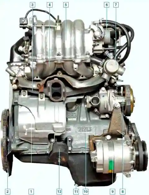
View of the engine on the right: 1 - starter shield; 2 - flywheel; 3 - exhaust manifold; 4 - inlet pipe; 5 - receiver; 6 - throttle assembly; 7- thermostat; 8 - coolant pump; 9 - air conditioner compressor; 10 - cylinder block; 11 - drain plug of the oil pan; 12 - right support of the power unit
The cylinder block of the engine is cast from special low-alloy cast iron, the cylinders are bored directly in the block.
Nominal cylinder diameter - 82.00 mm, machining tolerance + 0.05 mm.
The calculated minimum clearance between the piston and the cylinder (for new parts) should be 0.025-0.045 mm.
It is defined as the difference between the minimum cylinder diameter and the maximum piston diameter and is ensured by installing a piston of the same class as the cylinder into the cylinder.
For this, cylinders and pistons, depending on the dimensions obtained during machining, are divided into five classes through 0.01 mm.
The class of the cylinder in accordance with its diameter is marked in Latin letters on the lower plane of the cylinder block: A - 82.00-82.01, B - 82.01-82.02, C - 82.02-82.03, 13 - 82.03-82.04, E - 82.04-82.05 mm.
When repairing, the cylinder diameter can be increased by boring 04 or 08 mm for oversized pistons.
The maximum allowable cylinder wear is 0.15 mm per diameter.
In the lower part of the cylinder block there are five crankshaft main bearing supports with removable covers, which are attached to the block with special bolts.
The bores in the cylinder block for the bearings are machined with the covers installed, so the covers are not interchangeable and are marked with risks on the outer surface to distinguish them.
On the end surfaces of the rear support there are nests for thrust half rings that prevent axial movement of the crankshaft.
A steel-aluminum semi-ring (white) is installed in front, and a cermet (yellow) is installed in the back. In this case, the grooves on them should face the crankshaft.
Half rings are supplied in nominal and 0.127 mm larger sizes.
If the axial clearance (backlash) of the crankshaft is beyond 0.06-0.26 mm, then one or both half rings must be replaced (the maximum allowable axial clearance of the crankshaft in operation is 0.35 mm).

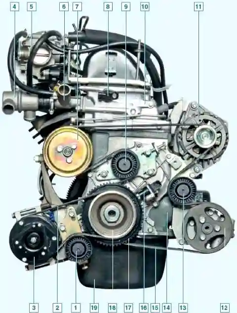
Front view of the engine: 1 - tension roller of the air conditioning compressor drive belt; 2 - air conditioning compressor drive belt; 3 - air conditioning compressor clutch; 4 - thermostat; 5 - throttle assembly; 6 - outlet pipe of the cooling jacket; 7- coolant pump pulley; 8 - phase sensor, 9 - tension roller of the auxiliary drive belt; 10 - cylinder head; 11- generator; 12 - pulley of the power steering pump; 13 - support roller of the auxiliary drive belt; 14 - cylinder block; 15 - auxiliary drive belt; 16 - crankshaft position sensor; 17 - auxiliary drive pulley; 18 - air conditioning compressor drive pulley; 19 - oil pan
Inserts of the main and connecting rod bearings of the crankshaft are thin-walled steel-aluminum.
The upper main bearing shells of the first, second, fourth and fifth bearings have a groove on the inner surface, and the upper shell of the third bearing and the lower shells installed in the covers are without a groove.
Repair inserts for main and connecting rod bearings are available for crankshaft journals reduced by 0.25, 0.5, 0.75 and 1.00 mm.
The nominal calculated diametrical clearance between the crankshaft journals and the bearing shells should be:
- - for main bearings - 0.026-0.073 mm (maximum allowable clearance - 0.15 mm);
- - for connecting rod bearings - 0.02-0.07 mm (maximum allowable clearance - 0.1 mm).
Crankshaft - made of ductile iron, has five main and four connecting rod journals.
The shaft is equipped with eight counterweights cast integrally with the shaft (full counterweight).
To supply oil from the main journals to the connecting rods, channels are drilled in it, closed with pressed and caulked plugs.
These channels also serve to clean the oil: under the action of centrifugal force, solid particles and resins that have passed through the filter are thrown to the plugs.
Therefore, when repairing the shaft and when balancing, it is necessary to clean the channels from accumulated deposits.
Plugs cannot be reused - they are replaced with new ones.
At the front end (toe) of the crankshaft, on a segment key, an asterisk is installed that drives the gas distribution mechanism (timing), and a pulley for driving auxiliary units (alternator, power steering pump and coolant pump), which is also a damper for torsional vibrations of the crankshaft .
On a vehicle with air conditioning, the A/C compressor drive pulley is attached to the accessory drive pulley with the crankshaft nut.
Auxiliary drive pulley has a ring gear for reading information by the crankshaft position sensor.
The crown has 58 teeth (the circumference of the crown is divided into 60 teeth, but two are missing, forming a cavity - this is necessary to obtain a synchronization pulse with each revolution of the crankshaft).
On the outer cylindrical surface of the pulley, the front crankshaft oil seal installed in the timing cover cast from aluminum alloy runs.
The timing cover has a boss with a hole for the crankshaft position sensor.
The rear oil seal is pressed into a die-cast aluminum holder that attaches to the rear end of the cylinder block.
The oil seal works on the surface of the crankshaft flange.
The front bearing of the input shaft of the gearbox is pressed into the rear end of the crankshaft.
A flywheel is attached to the crankshaft flange with six bolts through a common washer.
It is cast from cast iron and has a pressed steel ring gear for starting the engine with a starter.
The flywheel is installed so that the cone-shaped hole near its crown is opposite the connecting rod journal of the 4th cylinder - this is necessary to determine the TDC after assembling the engine.

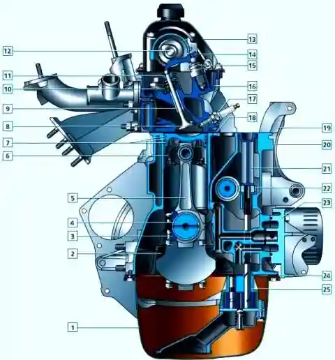
Cross section of the engine: 1 - oil pan; 2 - main bearing cover; 3 - connecting rod cover; 4 - crankshaft; 5 - connecting rod; 6 - piston; 7- piston rings; 8 - valve; 9 - valve guide sleeve; 18 - valve springs; 11 - plate; 12 - camshaft; 13- cylinder head cover; 14 - valve lever; 15 - hydrosupport; 18 - cylinder head; 17 - spark plug; 18 - cylinder head gasket; 19 - generator bracket; 28 - cylinder block; 21 - oil pump gear lock; 22 - oil pump gear; 23 - oil filter bracket; 24 - gasket of the oil pan; 25 - oil pump
Connecting rods - steel, I-section, processed together with covers.
In order not to confuse the covers during assembly, the cylinder number is stamped on them, as well as on the connecting rods (it must be on the same side of the connecting rod and the cover).
Special bolts are pressed into the holes of the lower head of the connecting rod; when disassembling, they must not be knocked out of the head.
A steel-bronze bushing is pressed into the upper head of the connecting rod.
According to the diameter of its hole for the piston pin, the connecting rods are divided into three classes with a pitch of 0.004 mm (the same as the pistons).
The class number is stamped on the top end of the connecting rod.
I also subdivide the connecting rodsare divided into 9 classes by weight, which are marked with paint of different colors on the rods of the connecting rods.
All engine connecting rods must be of the same mass class, i.e. marked with paint of the same color.
Piston pin - steel, tubular section, floating type (rotates freely in the piston bosses and in the connecting rod head), is fixed from falling out by two locking spring rings located in the grooves of the piston bosses.
Three classes of fingers are distinguished by the outer diameter (through 0.004 mm), which are marked with paint:
- 1 - blue (21.970-21.974 mm), 2 - green (21.974-21.978 mm), 3 - red (21.978-21.982 mm).
Piston - cast aluminum alloy.
The piston skirt has a complex shape: it is barrel-shaped in longitudinal section, and oval in transverse section.
Three grooves for piston rings are machined in the upper part of the piston.
The oil scraper ring groove has drillings for supplying oil collected by the ring from the cylinder walls to the piston pin.
The hole for the piston pin is displaced by 1.2 mm from the diametral plane of the piston, therefore, when installing the piston, it is necessary to follow the embossed arrow on its bottom: it must be directed towards the crankshaft pulley.
According to the outer diameter (nominal size), the pistons are divided into 5 classes: A - 81.965-81.975, B - 81.975-81.985, C - 81.985-81.995, D - 81.995-82.005, E - 82.005-82.015 mm. The piston class is stamped with a letter on its bottom.
At oversized pistons, a triangle (increase in diameter by 04 mm) or a square (increase in diameter by 0.8 mm) is knocked out on the bottom.
Pistons of three classes are supplied as spare parts - A, C and E (nominal and repair sizes), which is quite enough to match the piston to the cylinder.
In this case, it is not recommended to install a new piston in a worn cylinder without boring the cylinder.
The groove for the upper piston ring in the new piston may be slightly higher than in the old one, and the ring will break on the "step" formed in the upper part of the cylinder when it is worn.
According to the diameter of the hole for the piston pin, pistons are divided into 3 classes: 1-21.982-21.986, 2-21.986-21.990, 3-21.990-21.994 mm.
The class number is also stamped on the piston head.
For new parts, the class of the pin holes in the connecting rod and piston must be identical to the class of the pin.
Engine pistons are produced in the same weight class, so there is no need to select them separately.

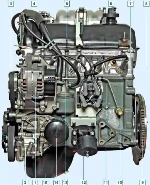
View of the engine on the left: 1 - generator; 2 - power steering pump; 3 - auxiliary drive belt; 4 - cylinder head cover; 5 - oil level indicator; 6 - oil filler cap; 7 - cylinder head; 8 - spark plug; 9 - flywheel; 10 - low oil pressure warning lamp sensor, 11 - ignition coil; 12 - left support of the power unit; 13 - oil separator of the crankcase ventilation system; 14 - oil filter; 15 - oil pan
Piston rings are located in the piston grooves.
The top two rings are compression rings. They prevent the breakthrough of gases into the crankcase and remove heat from the piston to the cylinder.
The lower piston ring is oil scraper.
The nominal clearance in height between the piston rings and the grooves in the piston (measured with a set of feeler gauges) should be:
- - for the upper compression ring - 0.04-0.07 mm; for the bottom - 003-006 mm;
- - for oil scraper - 0.02-0.05 mm.
The maximum permissible gaps for wear are 0.15 mm.
The gap in the lock for all piston rings should be 0.25-0.45 mm.
The gap is measured with a set of feeler gauges by inserting the ring into a special gauge or into the engine cylinder and aligning it with the piston head.
Cylinder head - made of aluminum alloy, common to all four cylinders.
It is centered on the cylinder block with two bushings and secured with 11 bolts.
If the bolt shaft is longer than 117 mm, it should be replaced with a new one.
A non-shrink metal-reinforced gasket is installed between the block and the head.
Reuse of the gasket is not allowed.
In the upper part of the cylinder head, an aluminum camshaft bearing housing is fixed on nine studs.
It is centered on two bushings put on the outer studs.
The gap between the camshaft journals and the housing bearings must not exceed 0.2 mm.
Camshaft - cast iron with chilled cams, five-bearing; is driven by a single-row roller chain from the crankshaft sprocket.
Axial movement is limited by a thrust flange included in the groove of the front bearing journal.
There are marks on the sprockets for the correct installation of the valve timing.
In this case, the mark on the crankshaft sprocket should align with the projection on the cylinder block, and the mark on the camshaft sprocket should align with the projection on the bearing housing.
The camshaft sprocket is mounted on the shaft in only one position and is tightened with a bolt with support and locking washers.
The tendril of the latter enters the hole in the sprocket, and the side part is bent to the edge of the bolt head.
A metal element is riveted to the sprocket - the phase sensor setpoint.
Saddles and valve guides are cast iron, pressed into the cylinder head.
Repair sleeves with an outer diameter increased by 0.2 mm are supplied as spare parts.
The holes in the bushings are finished with a reamer after pressing.
The bore diameter of the inlet valve bushings is 8.022-8.040 mm, the exhaust valves are 8.029-8.047 mm.
On the inner surface of the sleeve, grooves for lubrication are cut: at the inlet valve sleeve - for the entire length, at the exhaust valve - up to half the length of the hole.
On top of the bushings, metal-rubber oil deflector caps (valve seals) with a bracelet steel spring are put on.
The gaps between new guide bushings and valve stems should be within 0.022-0.055 mm for intake valves and 0.029-0.062 mm for exhaust valves (the limiting gap during wear during operation is 0.3 mm).
Valves - steel; exhaust - with heads made of heat-resistant steel, with welded chamfers.
The valves are arranged in a row, obliquely to the plane passing through the axes of the cylinders.
The diameter of the intake valve disc (37 mm) is larger than the exhaust valve (31.5 mm).
The valves are driven from the camshaft cams through levers (“rockers”).
Clearances in the valve drive are not adjustable.
With one end, the lever rests on the spherical head of the hydraulic support (gap gap compensator), and with the other end it acts on the end of the valve stem.
The engine is equipped with INA hydraulic mounts, which differ in design from the previously used hydraulic mounts.
First, a steel sleeve (body) is screwed into the cylinder head, and a support is already inserted into it on a sliding fit.
With this method of assembly, the possibility of deformation of the precision pair of hydrosupports is excluded.
To supply engine oil under pressure to the hydraulic bearings, four aluminum spacers are installed between the hydraulic bearing housings and the cylinder head - one spacer for the hydraulic bearings of two valves of each cylinder.
Through the channel of the cylinder block and the head of the block, the oil enters the camshaft bearing housing, and then along the tubular steel ramp to the spacers of the valve hydraulic bearings.
Ramp tube connections with spacers are sealed with rubber bushings.
The use of INA hydraulic bearings entailed the use of new valve levers, in which the diameter of the supporting sphere has decreased - from 12 mm (for the previous levers) to 11 mm.
The valve closes under the action of two oppositely coiled springs installed coaxially (coaxially).
They rest with their lower ends on support washers, and with their upper ends on a plate, which is fixed with two conical crackers that enter the groove at the end of the valve stem.
To reduce oscillations of the timing chain, a plastic damper is installed on its left branch between the oil pump drive shaft sprocket and the camshaft sprocket.
The right branch of the chain is tensioned by a spring-hydraulic tensioner installed in the cylinder head.
Pre-tensioning of the chain (when the engine is not running) is provided by a spring, working (after starting the engine) is provided by pressurized oil.
Oil is supplied to the hydraulic tensioner through a seamless steel tube with a diameter of 6 mm with tips.
This line starts from the threaded hole on the left wall of the cylinder block, into which the emergency oil pressure sensor fitting is screwed.
Properly chosen bending stiffness of the tube made it possible to weaken its vibrations, besides, metal holders with rubber inserts are used to suppress vibration.
The tip of the tube is attached to the body of the tensioner using a fitting bolt, which is used to fasten the front brake hose of rear and all-wheel drive VAZ cars.
The tensioner plunger presses on the shoe, which, like the chain guide, is made of wear-resistant plastic.
The tensioner shoe pivots on an axle located at the bottom of the cylinder block, to the right of the crankshaft sprocket.
The oil pump drive shaft is also driven from the timing chain.
The fastening of its sprocket (30 teeth) is similar to the fastening of the camshaft sprocket (38 teeth).
The roller rotates in the bushings, spread laid in the cylinder block, and is kept from axial movements by a thrust flange included in the groove on its front neck.
The ring gear of the roller engages with the oil pump drive gear mounted vertically in the sleeve of the cylinder block.
The gear has a slotted longitudinal hole, into which the splined shank of the oil pump shaft enters from below.
Oil pump - gear, single stage, with pressure reducing valve; mounted in a housing fixed at the bottom of the cylinder block.
The suction pipe is molded integrally with the lower part of the body and is closed with a stamped mesh for coarse oil cleaning from mechanical impurities.
Nominal clearances in the oil pump should be:
- - between gear teeth - 0.15 mm (maximum value - 0.25 mm);
- - between the gears (along the outer diameter) and the walls of the pump housing - 0.11-0.18 mm (maximum allowable value - 0.25 mm);
- - between the ends of the gears and the plane of the housing - 0.066-0.161 mm (maximum value - 0.20 mm);
- - between the driven gear and its axis - 0.017-0.057 mm (maximum value - 0.10 mm);
- - between the pump shaft and the hole in the housing - 0.016-0.055 mm (maximum value - 0.10 mm).
Engine lubrication - combined.
Under pressure, oil is supplied through the filter to the main and connecting rod bearings of the crankshaft, the hydraulic bearings of the valve levers, the hydraulic chain tensioner, the camshaft bearings and the bushing of the oil pump drive shaft.
By spraying, oil is supplied to the cylinder walls (further to the piston rings and fingers), to the camshaft cam pairs - lever, chains and valve stems.
Oil filter - full-flow, non-separable, with bypass and anti-drain valves.
Crankcase ventilation system — closed, forced. Under the action of vacuum in the intake pipeline of a running engine, gases from its crankcase through the oil separator enter the intake tract through the hoses of two circuits.
Through a hose (larger diameter) of the main circuit, crankcase gases are discharged at partial and full engine load modes into the space in front of the throttle valve.
Through the hose of the idle circuit, crankcase gases are discharged into the space behind the throttle valve both at partial and full engine loads, and at idle.


