K9K TURBO engine - supercharged, in-line, liquid-cooled, four-cylinder, with ONS valve timing
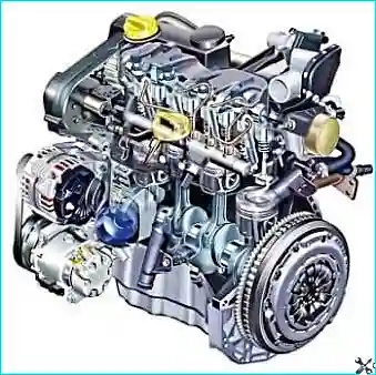
The cylinder head of the diesel engine is made of aluminum alloy.
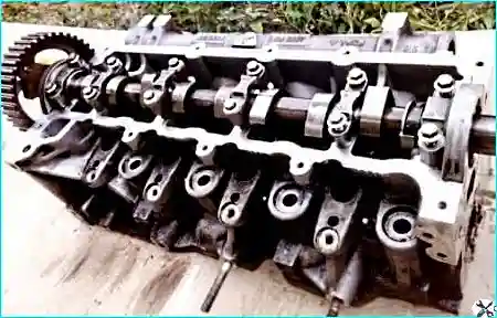
The cylinder head gasket is made of metal, making it more resistant to high temperature and pressure.
The engine block is cast in gray cast iron with cylinder liners already formed.
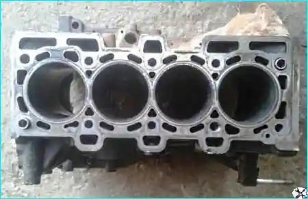
Crankshaft bearings have cast iron caps included in the block, including bolts
In both parts of the bearings, liners are inserted.
The liners have tongue locks and lubrication grooves along the central circumference.
The engine camshaft is installed in a bed of bearings made in the body of the head, and is fixed from axial movement by thrust flanges.

The crankshaft rotates in main bearings with thin-walled steel liners with an anti-friction layer
The axial movement of the crankshaft is limited by two half rings installed in the grooves of the bed of the middle main bearing.
The oil passages to the bearings run transversely (diagonally).
The cast iron flywheel is mounted on the rear end of the crankshaft and secured with six bolts.
A gear rim is pressed onto the flywheel for starting the engine with a starter.
Pistons are made of aluminum castings.
In the bottom of the piston on the side of the combustion chamber, a recess with a guide rib is made, which ensures the vortex movement of the intake air and, as a result, very good mixture formation
A special cooling circuit keeps the piston cool during the exhaust stroke.
Friction in the piston group is reduced due to the graphite coating of the piston skirt.
The piston pins are installed in the piston bosses with a gap and are pressed with an interference fit into the upper heads of the connecting rods, which are connected with their lower heads to the connecting rod journals of the crankshaft through thin-walled liners, similar in design to the main ones.
Due to the high maximum cycle pressure, the diameter of the piston pin is increased.
Steel connecting rods, forged, with an I-section shank.
The connecting rod and its cover are made from a single blank and processed in one piece, after which the cover is chipped from the connecting rod using a special technology
The result is the most accurate fit of the cover to its connecting rod.
In this case, the installation of a cover on another connecting rod is unacceptable.
Combined lubrication system. oil flow.
Oil from the oil sump is sucked in by the oil pump, passes through the oil filter and is pressurized into the engine
The oil pump with overpressure valve is driven by a roller chain from the crankshaft sprocket
Under the crankshaft of the engine there is an oil deflector that prevents the oil from overflowing quickly
The aluminum alloy crankcase is integrated with the front and rear covers and together with them is attached to the engine block.
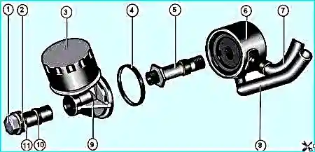
Oil filter and oil heat exchanger of the K9K engine: 1 — oil filter bracket mounting bolt; 2,10,11 - sealing rings; 3 - oil filter; 4 - sealing ring of the heat exchanger; 5 - heat exchanger fastening bolt; 6 - heat exchanger; 7.8 - oil pipelines; 9 - oil filter bracket
An oil heat exchanger 6 and an oil filter 3 are also embedded in the lubrication system (Fig. 5)
An overpressure valve is also fixed in the oil filter housing, which provides the possibility of reverse oil bypass.
The oil filter is equipped with a replaceable paper filter element.
The engine cooling system is sealed, with expansion tank, consists of a cooling jacket, made in casting and surrounding the cylinders in the block, combustion chambers and gas channels in the cylinder head
The forced circulation of the coolant is provided by a centrifugal water pump driven by a crankshaft by an accessory drive belt
To maintain the normal operating temperature of the coolant, a thermostat is installed in the cooling system, which closes a large circle of the system when the engine is cold and the coolant temperature is low.
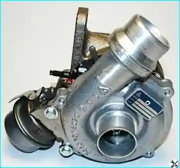
Turbocharging and exhaust gas recirculation system.
The exhaust manifold is attached to the turbocharger flange with nuts
A turbocharger is used to increase the air pressure by means of a turbine, which is driven by exhaust gases.
Turbine bearing lubrication is included in the overall engine lubrication system.
The turbocharging system has been supplemented with an exhaust gas recirculation system.
The amount of exhaust gases supplied to the system is regulated by the EGR solenoid valve, the cone-shaped pusher of which changes the cross section of the bypass hole at different valve positions.
Power system
Clean air is sucked into the cylinders of a diesel engine when the piston moves down
During the compression stroke, the pressure in the cylinder rises sharply, while the temperature in it becomes higher than the ignition temperature of diesel fuel
If the piston is before TDC, then diesel fuel is injected into the cylinder heated to a temperature of + 700-900˚C, which ignites spontaneously, so spark plugs are not required.
However, when starting the engine after a long period of inactivity (cold), especially if the air temperature is low, simple compression is often not enough to ignite the combustible mixture.
For this case, glow plugs are installed in the combustion chamber, which are located so that the jet of fuel from the nozzle atomizer hits the hot tip of the candle and ignites.
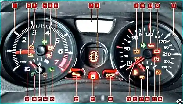
The glow plugs automatically turn on the moment immediately before the starter is turned on.
At the same time, signaling device 9 turns on in the instrument cluster (see Fig. 7), and the glow plugs begin to heat up to a high temperature.
The main purpose of heating the spark plugs is to ignite the fuel injected into the cylinder.
After heating the candle to the required temperature (usually it takes a few seconds), the indicator goes out and the engine can be started
Usually, the warning lamp goes out faster, the higher the temperature of the engine.
Immediately before starting the engine (or most often shortly after), the glow plugs are switched off
In most modern engines, they can continue to run for up to several minutes after starting to reduce harmful emissions into the atmosphere when the engine is running cold, as well as to stabilize the combustion process in an engine that is not yet fully warmed up.
Then the current supply to the candles stops.
Thus, the start-up of the diesel engine and its further operation directly depend on the correct operation of the glow plugs.
Fuel is supplied by a high pressure fuel pump (TNVd) directly from the fuel tank.
In the fuel injection pump, the fuel is compressed before injection, then fed into the engine cylinders in the order of their operation
At the same time, the fuel pump regulator measures the fuel depending on the position of the gas pedal.
Diesel fuel is injected through injectors at a certain point in time into the prechamber of the corresponding cylinder
Due to the shape of the prechamber (vortex chamber), the incoming air receives a certain swirl during compression, as a result of which the fuel is optimally mixed with air.
Before fuel enters the injection pump, it passes through a fuel filter, where it is cleaned of contaminants and water.
That is why it is important to replace the filter in a timely manner, according to the regulations.
TNVd does not require maintenance. All moving parts of the pump are lubricated with diesel fuel.
Injection pump is driven from the crankshaft pulley by a toothed belt.
Since self-ignition of the combustible mixture occurs in a diesel engine, an ignition system is not required, and a solenoid valve is installed in the injection pump
To stop the engine, the voltage supply to the solenoid valve is interrupted and the valve closes the fuel channel, due to which the fuel supply is stopped and the engine stops
When in When the starter is turned on, voltage is applied to the solenoid valve and it opens the fuel channel.
Engine specifications:
- - compression ratio - 18.25;
- - cylinder diameter - 76;
- - piston stroke - 80.5;
- - engine displacement - 1461 cm3;
Tightening torques for engine parts (daNm)
- Cylinder head bolts - According to the scheme 2.5 daNm then turn 255˚±10˚
- Camshaft bearing cap bolts 1
- Camshaft sprocket bolt - 3 + 84°
- Vacuum pump mounting bolts 2.1
- Thermostat unit mounting bolts on cylinder head 1
- 2.6 exhaust manifold stud nuts
- 2.1 EGR valve bolts
- Glow plugs 1.5
- Injection pump mounting bolts 2.1
- Injector flange bolt 2.8
- 2.8 fuel rail mounting bolts
- 3.8 high pressure fuel line fitting
- Cylinder head cover bolts 1
- Stud nuts for fastening the pipe manifold to the exhaust manifold 2.6
- 0.9 turbocharger oil return pipe fitting
- 2.3 turbocharger oil supply pipe fitting
- Timing idler roller bolt 2.5
- TDC retainer hole plug 2
- Cylinder head pendulum mounting bolts 2.1
- 4.5 heat exchanger connection nipple
- 4.5 oil filter bracket bolts
- Crankshaft bearing cap bolts 2.7 + 47° ± 5°
- Nuts for connecting rod cap bolts 2 + 45° ± 6°
- Knock sensor 2
- Oil level sensor 2.2
- Oil pump mounting bolts 2.5
- Engine oil pan bolts - See procedure
- Water pump mounting bolts 1.1
- Flywheel mounting bolts 5 to 5.5
- Clutch cover bolts 0.8
- Pulley bolt 2 + 130° ± 15°
- Water pump inlet pipe bolt 2
- Multifunction bracket 4 mounting bolts
- Alternator mounting bolts 2.1
- 2.1 power steering pump mounting bolts
- A/C compressor bolts 2.1


