Turbocharger (turbocharger) is removed during engine repair, replacement of gaskets, and when replacing the turbocharger itself
Turbocharger is not allowed to be disassembled and repaired.
Turbocharger condition should be checked by rotor run-out time when diesel engine is stopped.
For this, after 3...5 minutes of operation at minimum idle speed, diesel engine is brought to maximum speed mode, after which fuel supply is turned off.
Turbocharger rotor rotation after diesel engine is stopped should be heard for at least 5 s.
Even, constant level sound with gradual attenuation indicates normal condition of turbocharger,
One of the reasons for decreased diesel power and increased smoking may be a decrease in pressure boost due to contamination of the compressor flow path, which can be determined by the tight rotation of the rotor.
If the rotor rotates tightly, it is necessary to partially disassemble the turbocharger and flush the compressor part.
Removing the turbocharger
Disconnect the negative terminal of the battery
Clean the surface and the oil supply fittings to the turbocharger.
Apply penetrating liquid to the nuts and bolts connecting the turbocharger to the exhaust manifold.
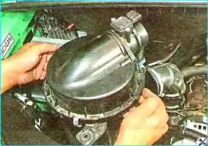
Removing the air filter
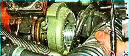
Removing the air supply hose
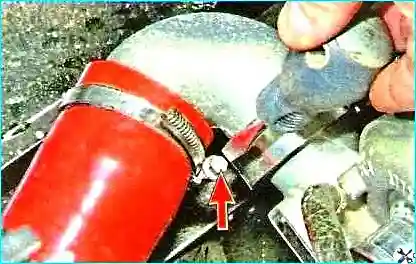
Loosen the clamp securing the pipeline to the turbocharger adapter
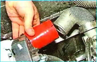
Disconnect the pipeline
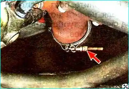
Unscrew the nut of the clamp securing the neutralizer inlet pipe to the turbine pipe adapter and slide the clamp along the pipe
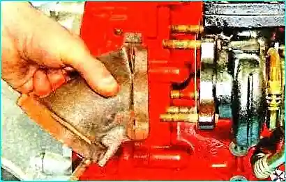
Unscrew the fastening nuts and remove the turbine pipe adapter
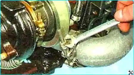
Loosen the fastening clamp
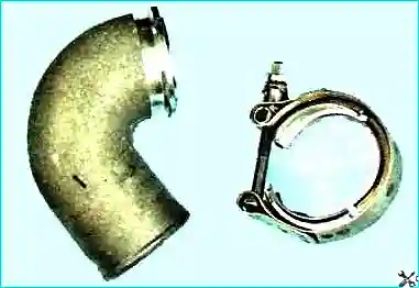
Removing the pipeline adapter from the turbocharger to the cooler
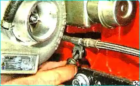
Unscrew the bolt securing the oil supply hose holder
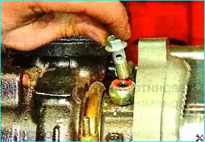
Unscrew the bolt securing the hose tip
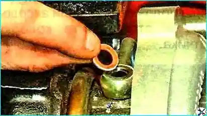
Disconnect the hose and remove the sealing washers
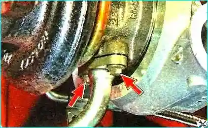
Unscrew the two bolts securing the flange of the oil drain pipe from the turbine bearing
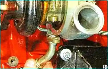
Disconnect the tube from the turbocharger housing
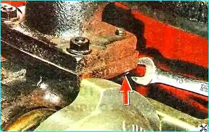
Unscrew one bolt
Unscrew the three nuts securing the turbocharger to the exhaust manifold
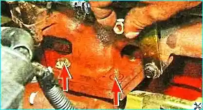
Removing the turbocharger.
Checking the operation of the bypass valve drive.
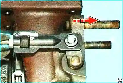
To do this, move the rod (arrow in the figure), the valve lever should move smoothly, without jamming, and after releasing the rod should return to initial position.
Checking the adjustment of the bypass valve drive
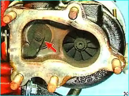
In a free state, it should be tightly pressed against the seat.
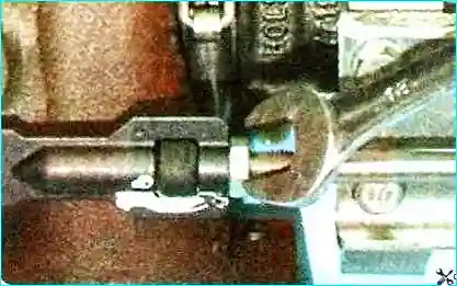
If the valve does not fit tightly to the seat, then loosen the lock nut
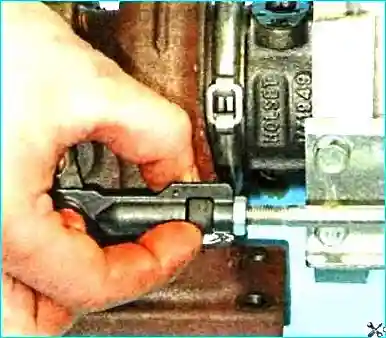
Turning the adjusting nut, we achieve the desired valve position.
After adjustment, tighten the lock nut and check the tightness of the valve fit.
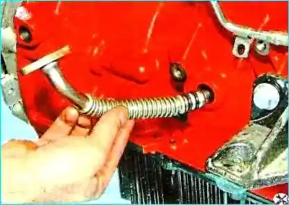
If necessary, remove the tip of the oil drain tube from the turbine bearing from the hole in the cylinder block.
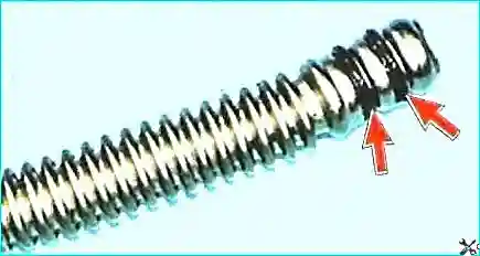
Install new rubber sealing rings on the tube tip.
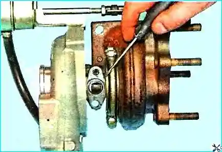
Disconnect the oil drain pipe flange seal from the housing
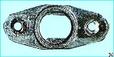
Replacing the seal. Clean the mating surfaces of the turbocharger, exhaust manifold and inlet pipe.
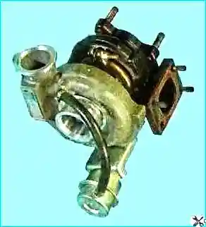
Install the turbocharger in the reverse order.
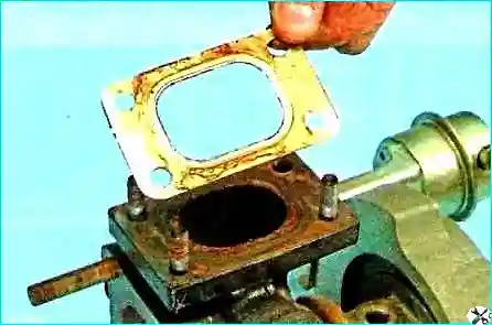
Replacing the gasket connecting the turbocharger to the exhaust manifold
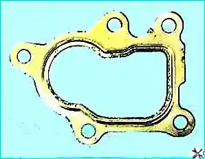
Replacing the gasket between the turbine adapter
Assemble all parts in reverse order.
Before installing the turbocharger, apply a thin layer of graphite grease to the turbocharger mounting studs.
Tightening torque of three mounting nuts and one bolt for mounting the turbocharger to the exhaust manifold is 24 Nm.


