In the article, we will consider methods for troubleshooting engine parts before assembly
After disassembling the engine, which was described in the previous article, thoroughly wash the engine parts with kerosene and blow with compressed air
We inspect the cylinder block, especially carefully inspect the crankshaft bearings
Cracks in any part of the block are not allowed
Checking the tightness of the block
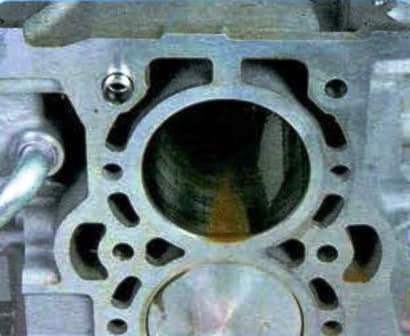
Inspecting the cylinders on both sides.
Scratches, scuffs and cracks are not allowed
We determine the actual diameters of the cylinders with a bore meter
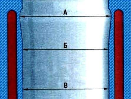
Cylinder diameter is measured in three zones
In each belt, we measure the diameter in two mutually perpendicular directions (longitudinal and transverse)
In the area above the belt (A) at a distance of 5 mm from the plane of the connector with the block head, the cylinders practically do not wear out
By the difference in size in this zone and in the other zones, one can judge the wear of the cylinder
Nominal cylinder size is 81.01 mm
Maximum wear should not exceed 0.08 mm
Checking the flatness of the mating surfaces of the block and cylinder head
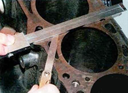
Applying a ruler to the surface:
- - in the middle of the block;
- -in transverse and longitudinal directions;
- - along the diagonals of the plane
In each position, we determine the gap between the ruler and the surface with a probe
If the deviation is greater than 0.1 mm, replace the block
Clean the bottom of the piston with a scraper
We clean the grooves for the piston rings from carbon deposits with a piece of the old ring, inserting it into the groove and rolling along the groove
We inspect the pistons, connecting rods, covers - they should not have cracks
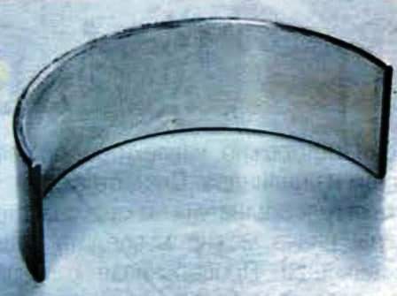
We examine the liners: if risks, scuffs and delamination of the antifriction layer are found on their working surfaces, we replace the liners with new ones
All connecting rod bearings are the same and interchangeable
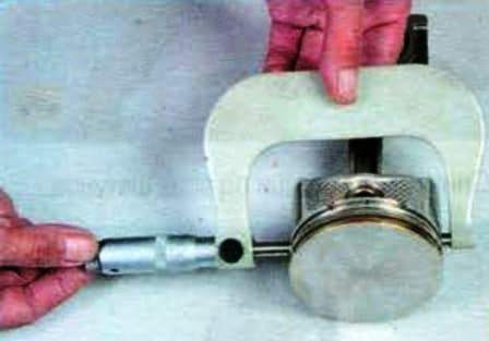
We measure the diameter of the pistons in a plane perpendicular to the axis of the piston pin, at a distance of 19 mm from the edge of the skirt
- Nominal size piston diameter for 1.8L engine is 83.0mm;
- For 2.0L engine - 87.5mm;
- For 2.5L engine - 89.0mm
Based on the measurement results, we determine the gap between the piston and the cylinder, if necessary, we select new pistons for the cylinders
The calculated clearance between the piston and the cylinder for new parts is 0.04 mm.
It is determined by measuring the cylinders and pistons and provided with the installation of pistons of nominal or repair sizes
If the clearance of a used engine is greater than this value, then the cylinder block and pistons are replaced
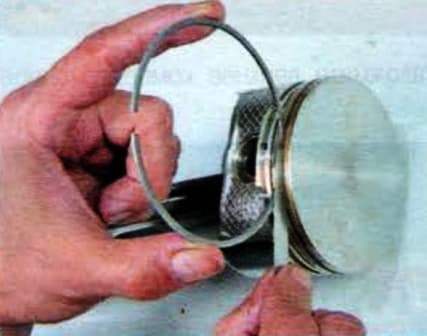
We check the height gap between the grooves in the piston and the rings with a flat feeler gauge, inserting the ring into the corresponding groove
Piston ring gaps:
- The nominal gap of the first compression ring is 0.03-0.08 mm
- Maximum allowable clearance of the first compression ring 0.17 mm
- The nominal clearance of the second compression ring is 0.03-0.07 mm
- Maximum clearance of the second compression ring 0.17 mm
- Nominal clearance of the oil scraper ring - 0.03-0.07 mm
- Maximum allowable clearance of the oil scraper ring 0.15 mm
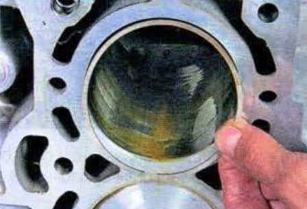
We install the ring in the cylinder to a depth of about 50 mm
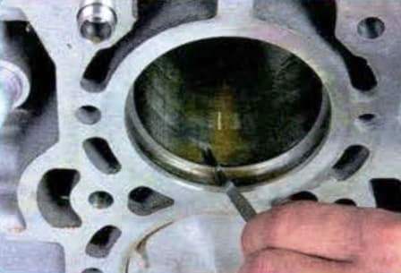
Check the thermal gap with a flat probe (clearance in the lock of the rings)
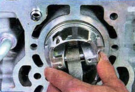
To install the ring without distortion, we move the ring deep into the cylinder with a piston
Piston ring clearances:
- The nominal clearance of the first compression ring is 0.16-0.31 mm
- Maximum clearance of the first compression ring 1.0 mm
- The nominal clearance of the second compression ring is 0.33-0.48 mm
- Maximum clearance of the second compression ring 1.0 mm
- Nominal clearance of the oil scraper ring - 0.20-0.70 mm
- Maximum allowable clearance of the oil scraper ring 1.0 mm
All pistons of nominal and repair sizes are made with a high degree of accuracy and do not require pre-sorting and selection by weight
If necessary, used pistons can be installed in individual cylinders if they are in good condition. The balancing of the engine in this case will not be disturbed
The lubrication gap in connecting rod bearings is measured in two ways:
First measurement method
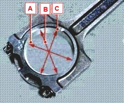
We measure the inner diameter of the lower head of the connecting rod assembly with the cover and the liner in three directions (A, B and C), tightening the cap fastening nuts to a torque of 25 Nm
Nominal inner diameter of the bottom end of the connecting rod 50.006-50.032 mm
Determine the ellipse of the lower head of the connecting rod as the difference between the larger and smaller measured values
If the ellipse is greater than 0.05 mm, replace the connecting rod together with the cover
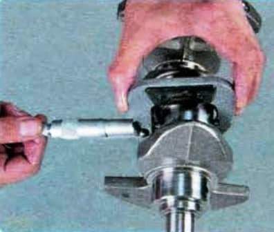
We measure the diameter of the connecting rod journals of the crankshaft with a micrometer
Nominal crankpin diameter 49.980 mm
The lubrication gap between the liners and the crankshaft journals is 0.026-0.052 mm
Second measurement method
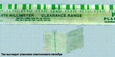
Plastigage can be used to measure the lubrication gap in connecting rod bearings
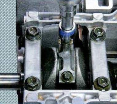
We unscrew the two nuts securing the connecting rod cover and remove it
We remove all dust and foreign particles from the connecting rod journal of the crankshaft and the working surface of the bearing
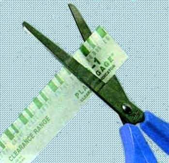
Cut off the caliber of the required size
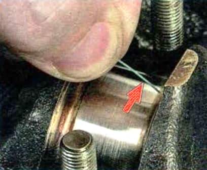
We put the plastic gauge on the connecting rod journal of the crankshaft
Carefully, so as not to shift the caliber, install the connecting rod cover on the connecting rod mounting studs
We tighten the connecting rod cap nuts with a torque of 30 Nm (3 kgcm)
We install the head of the socket wrench on the nut and mark the head with a felt-tip pen
Turn the nut 90º until the marks on the cover and socket head line up
We also tighten the second connecting rod cap nut
Unscrew the connecting rod cap nuts
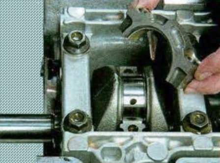
Remove the connecting rod cover
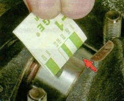
We apply a template and measure the width of the print on the crankshaft journal. It should be 0.026-0.052 mm
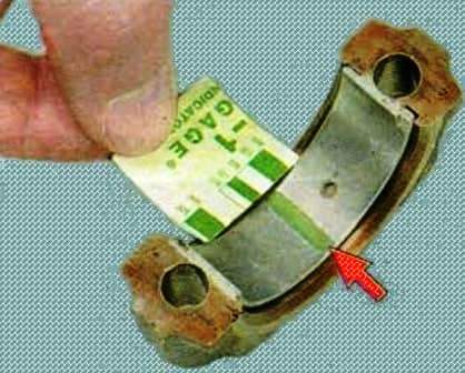
In the same way, we measure the width of the print on the connecting rod cover liner with a template
It is enough to measure the width only on one of the mating parts, according to the most convenient and readable print
Measuring the lubrication gap in the main bearings
The lubrication gap can be measured in two ways
First measurement method
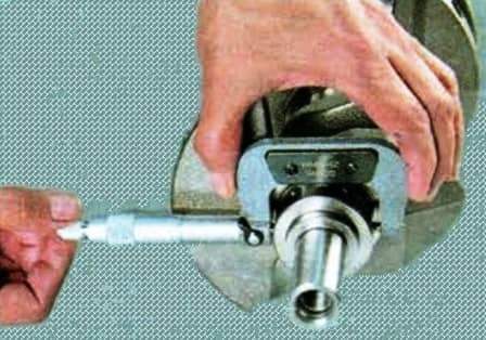
We measure the diameter of the crankshaft main journals with a micrometer
Nominal journal diameter 51.980-52.000 mm
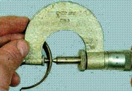
Measure the thickness of the main bearing shell with a micrometer
We measure the inner diameters of the holes for the main bearings with the liners installed with a inside gauge, tightening the bolts of the frame of the main bearing caps to a torque of 47-53 Nm (4.7-5.3 kgcm)
Nominal bore diameter for main bearings 51.999-52.032 mm
The lubrication gap between the main bearings and the crankshaft journals is 0.019-0.035 mm
Second measurement method
The plastic Plastigage can be used to measure the lubrication gap in the main bearings
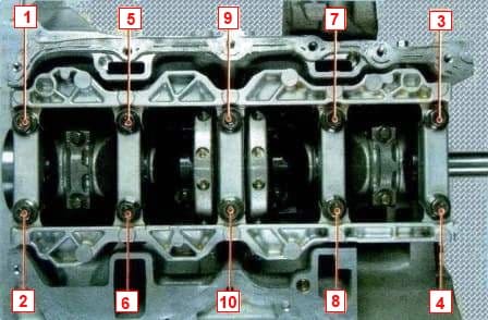
We unscrew the bolts of the main bearing caps in the order shown in the figure, and remove the cap

Cut off the caliber of the required size
We remove all dust and foreign particles from the crankshaft main bearing journals and the working surface of the cover bearing
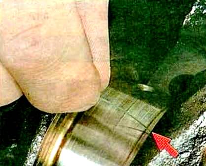
We lay the gauge in the direction of the axis of the crankshaft without blocking the oil hole
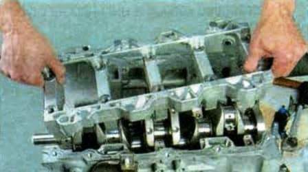
Carefully install the frame of the main bearing caps to prevent displacement of the gauges
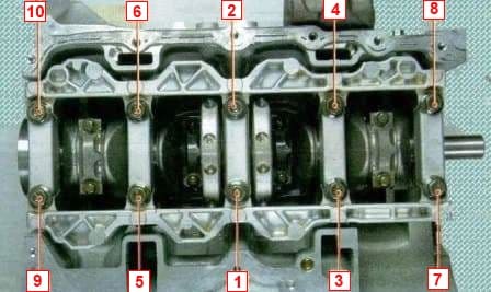
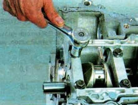
We screw in the bolts of the frame of the main bearing caps and tighten them with a torque of 47-53 Nm, in the order shown in the figure
We unscrew the bolts of the main bearing cap frame and remove the cap
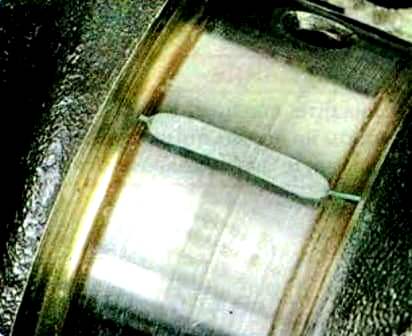
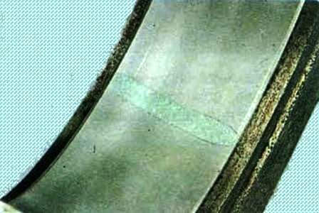
This is how the imprint of the plastic gauge on the crankshaft journal and main bearing looks like after crimping and removing the main bearing cap
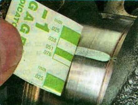
We apply the template to the crankshaft and measure the width of the print with a scale on its packaging, it should be 0.019-0.035 mm
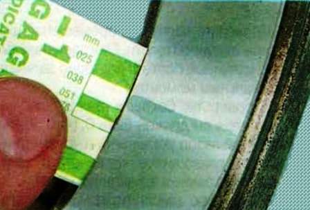
We also measure the width of the imprint on the main bearing cap
It is enough to measure the width only on one of the mating parts, according to the most readable print


