On the dashboard are installed: a speedometer, a combination of instruments and four signaling devices
Speedometer has an odometer of the car's total mileage
The instrument cluster combines: fuel gauge; coolant temperature gauge with built-in liquid overheat warning light; oil pressure indicator in the engine lubrication system with built-in alarm lamp for emergency oil pressure drop and voltmeter
The signaling devices inform about an emergency drop in the brake fluid level, the activation of the parking brake, high beam headlights and direction indicators
Removing control devices
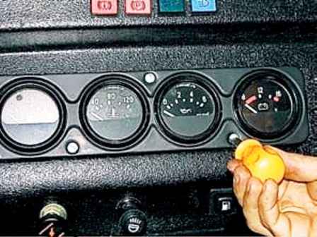
Unscrew the three screws with a screwdriver and remove the instrument cluster from the panel
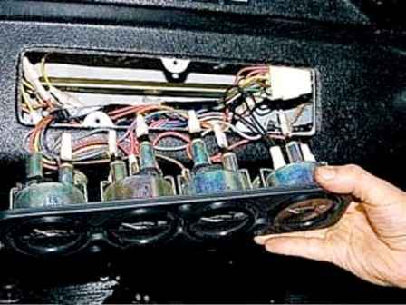
If you need to remove all devices from the shield, write down the order of connecting wires during disassembly
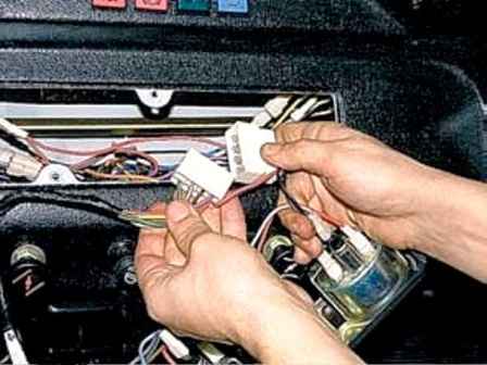
Disconnect the wiring harness from the instrument cluster
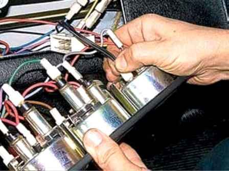
Disconnect the tip of the negative wire from the voltmeter
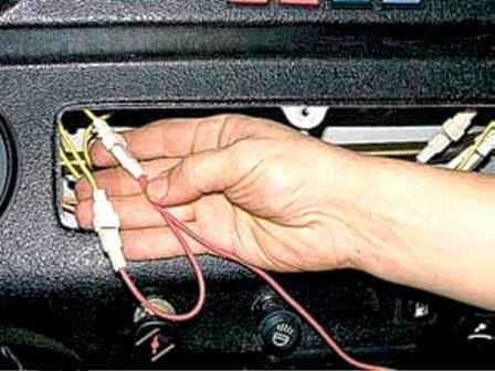
Disconnecting the ground wires
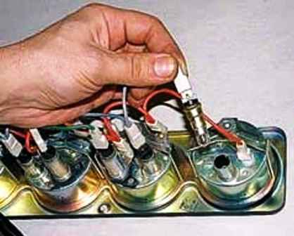
Remove the instrument cluster and take out the backlight
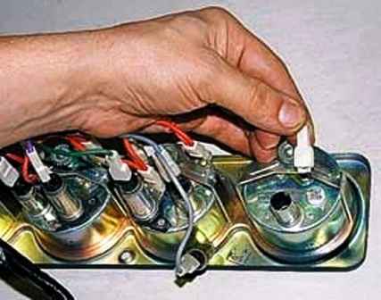
Remove the tip of the wire from the output of the voltmeter
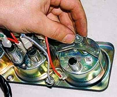
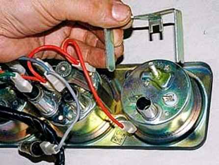
Unscrew the voltmeter fastening nut and remove the bracket
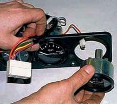
Remove the voltmeter from the shield
We remove the rest of the devices in the same way
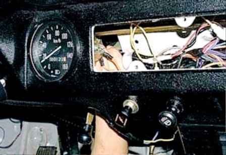
To remove the speedometer, unscrew the union nut of the flexible shaft of the speedometer drive under the instrument panel
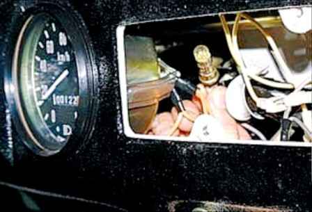
We take out the cartridge with the speedometer backlight
The speedometer is attached to the panel with two brackets
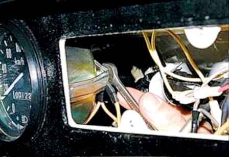
We unscrew the nut of the right and left studs of the speedometer housing with a key 8
Remove the earth wires from the right stud of the speedometer
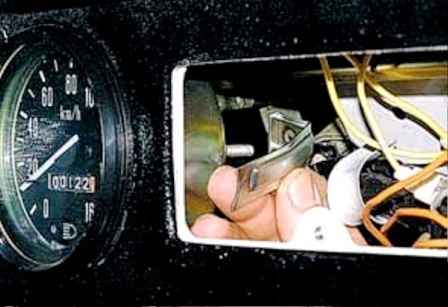
Remove the brackets from the studs and remove the speedometer from the instrument panel
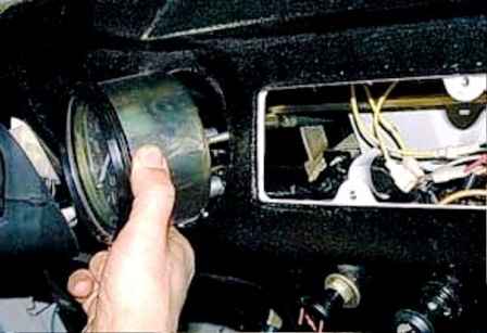
Install control devices in reverse order
Checking control devices and sensors
Speedometer
Speedometer - pointer, mechanically driven from the transfer case shaft.
It is checked on a special stand.
Of the possible malfunctions, you can independently eliminate the vibration of the arrow that occurs when the car is moving
To do this, disconnect the flexible shaft from the speedometer, remove it from the shell, wash it in kerosene and wipe it
Before installation, apply CIATIM-201 or No. 158 grease to the shaft.
If mechanical damage is found on the shaft, we replace it as an assembly.
If there are no readings on the gauges of the instrument cluster and the voltmeter, make sure that fuse No. 1 in the fuse box is working, and voltage is applied to terminals "B" of the instruments
Fuel gauge
The fuel gauge is electromagnetic, it works in conjunction with the BM-142-D (51.3827) sensor installed in each fuel tank.
The sensor is a rheostat with a nichrome wire resistor.
The moving contact of the rheostat is moved by the float lever.
You can check the correct adjustment of the fuel level indicator and its sensor without special equipment - by filling the tank from measuring glass
As the tank fills up, we compare the filled amount of fuel with the readings of the device.
Permissible error is no more than 7%.
If the readings are too high or too low on the entire scale evenly, then the error can be eliminated by bending the sensor float lever
If the pointer needle is constantly at the beginning of the scale (showing an empty tank), regardless of the amount of fuel in it and the position of the fuel level sensor switch, the pointer is faulty or the wire connecting it and the switch is shorted to ground
To check the pointer, remove the instrument cluster without disconnecting the wiring block from it
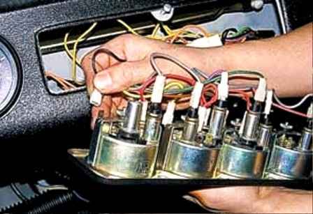
Remove the wire tip from the "D" terminal and turn on the ignition
If the arrow remains at the beginning of the scale, the fuel gauge is faulty.
Otherwise, check the integrity of the wire connecting it to the sensor switch
If the arrow is at the beginning of the scale when only one of the fuel level sensors is turned on, either the sensor itself is faulty, or the wire connecting it to the switch is shorted to ground
To check the fuel level sensor, remove the wire tip from its output.
If the arrow of the device has moved to the end of the scale, the sensor is faulty.
Otherwise, check the integrity of the wire connecting it to the sensor switch
If the pointer needle is constantly at the end of the scale, showing a full tank, regardless of the amount of fuel in it and the position of the switch, then either the device itself is faulty, or the wire connecting it to the fuel level sensor switch is damaged
To check the pointer, remove the shield from the instrument panel without disconnecting the wire block
Remove the wire tip from the "D" terminal and turn on the ignition
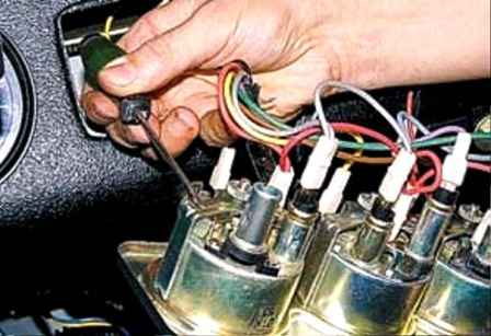
With a screwdriver we close the output "D" of the device to its body
If the arrow has not moved to the beginning of the scale, the pointer is faulty.
Otherwise, check the integrity of the wire connecting it to the sensor switch
If the arrow is at the end of the scale when only one of the fuel level sensors is turned on, it is faulty, either the sensor itself, or the wire connecting it to the switch is damaged, or the ground wire has a bad contact with the sensor
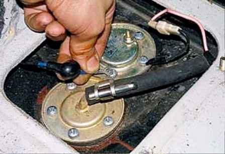
To check the fuel level sensor, remove the tip of the wire from its output and close it first to the sensor housing, and then to the body
If the arrow of the device in both cases remained at the end of the scale, you should check the integrity of the wire connecting it to the sensor switch
If the arrow deviated to the beginning of the scale only when the wire is closed to the body, then there is no sensor contact with the "ground". If the arrow moves in both cases, the sensor is faulty
Coolant temperature gauge
The coolant temperature gauge works in conjunction with the ТМ-106 temperature sensor screwed into the thermostat housing cover
The sensor has a thermistor (a resistor that changes its resistance depending on temperature)
You can check the serviceability of the temperature gauge and its sensor with a tester with a temperature gauge function or a mercury thermometer with a measurement scale limit of 0–100 °C
To do this, the sensor must be removed from the engine, and its wire should be extended so that the sensor on it can be lowered into a container of hot water
The sensor body should be connected with a wire to the car ground
Pour boiling water into the container and lower the thermocouple of the tester or thermometer into it
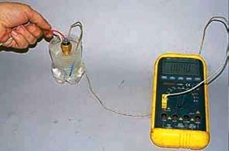
Immerse the sensor in water so that its output remains dry
Turn off the ignition.
As the water cools, we control its temperature and compare it with the readings of the pointer on the instrument panel
Indication error at 100 and 80 °C should not exceed ±5 °C, and at 40 °C +12 °C is allowed.
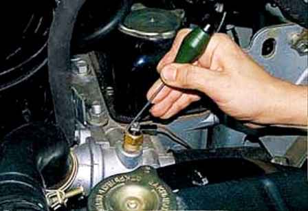
If the arrow of the device is constantly at the beginning of the scale, use a screwdriver to close the sensor output to ground
If the sensor is faulty, the arrow will deviate to the end of the scale.
If the arrow does not deviate, remove the instrument panel
Conclusion "D" of the temperature indicator is connected to the "mass".
If the arrow deviates, the device is working, but the wire between the sensor and the temperature indicator is damaged
If the arrow of the temperature gauge is constantly at the end of the scale, disconnect the wire tip from the sensor and isolate it
If the arrow returns to the top of the scale, the temperature sensor is defective.
Otherwise, remove the instrument cluster and disconnect the wire tip from the “D” terminal of the temperature gauge
If the arrow returns to the beginning of the scale, the device is working, and the wire connecting it to the sensor is shorted to ground
The temperature sensor and gauge are non-separable and cannot be repaired
Oil pressure gauge
The oil pressure indicator works in conjunction with the MM358 (or 23.3829) sensor of the engine lubrication system.
Indications of the pointer can be checked using a control pressure gauge installed in place of the sensor
You can check the sensor only on a special stand and by replacing it with a known good one.
If, with the ignition on, the pointer arrow is constantly in one of the extreme positions, then the pointer or oil pressure sensor is faulty, or the wire connecting them is damaged.
The cause of the malfunction can be determined by analogy with the temperature gauge (see above).
Voltmeter
Voltmeter can be checked by comparing its readings with the readings of the tester.
At 12V, the real voltage should not exceed 12.7V, at 14V, it should be less than 13.9V
Before testing, we recommend holding the voltmeter at 12V for about five minutes
Signals and signal lamps
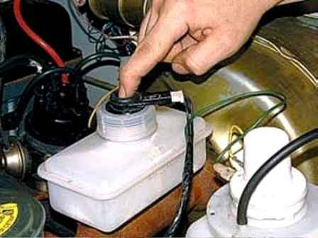
To check the signaling device for insufficient brake fluid level, turn on the ignition and press the rod of its sensor
The indicator lamp should light up
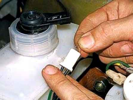
To check the health of the lamp, disconnect the wires from the sensor and close them
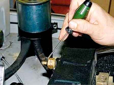
If the indicator lamp does not light up, replace it with a working one and repeat the test
To check the signal lamp for overheating of the coolant with a screwdriver, close the sensor output to ground
The TM111 coolant overheat sensor can be checked by analogy with the temperature sensor (see above).
The sensor contact must close at 92-98 °C.
The MM111 emergency oil pressure sensor can only be checked on a special stand. If a malfunction is suspected, we replace it with a new one


