The piston pin is installed with tension in the upper head of the connecting rod and rotates freely in the piston bosses.
The engines are equipped with SMP pistons.
Remove the piston rings using special piston ring pliers.

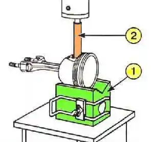
Install the piston assembly with connecting rod on the prism (1) of the Mot574-22 device (see Fig. 1).
Align the piston pin with the hole for its exit in the prism (1).
Using a press, press out the piston pin with the mandrel (2) of the Mot574-22 device.
After disassembling the connecting rod and piston group, it is necessary to carry out a number of measurements in order to reject worn parts.
Places of primary wear:
- - piston rings: they wear out during operation, in addition, they wear out along the width in the piston groove - change the rings as a set with each disassembly and assembly.
- Do not change the rings more often than necessary: this accelerates the wear of the cylinder in the block;
- - piston grooves for rings: if the width of the grooves is greater acceptable, then it is necessary to replace both the pistons and the rings;
- - piston skirt (part of the outer cylindrical surface of the piston, located below the axis of the piston pin):
- - during operation, the surface of the skirt located in the plane perpendicular to the axis of the piston pin wears out - it is necessary to replace the piston;
- - the hole of the piston pin in the piston breaks along the axis of the piston: if the gap is large - replace the piston;
- - bushing in the upper head of the connecting rod: if worn - replace the bushing;
- - piston pin: the place of contact with the head of the connecting rod and the place of contact with the piston bosses wear out. Should fit tightly (with tension) in the upper head of the connecting rod.
If worn, when replacing pistons, connecting rods, upper connecting rod bushings - replace the piston pins;
- - connecting rods are subject to compression and tension during operation, so they usually lose their shape (bend, twist), do not straighten such connecting rods - replace them immediately.
- - rarely, but it happens that a connecting rod breaks or stretches the lower head (on the connecting rod journal of the crankshaft) - replace damaged connecting rods.
The piston pin must match the diameter of both the upper head of the connecting rod and the hole for the piston pin.
The piston diameter must match the diameter of the cylinder in the block.
In assembled connecting rod + piston + piston rings units should not differ in weight by cylinders, a difference of no more than 6 g is permissible.
Otherwise, the engine will not operate smoothly enough, which over time leads to fatigue failure of parts.

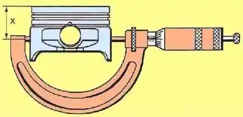
The piston diameter must be measured according to Figure 2.
The piston diameter is measured at a distance of X = 42.00±0.01 mm from the piston head.
The total height of the piston is 55 mm.
Piston size groups in Table 1.
Mark - Piston diameter, mm:
- A - 79.475±0.005;
- B - 79.485±0.005;
- C - 79.495±0.005
The piston pin is pressed into the upper head of the connecting rod and sits freely in the piston bosses.
Piston pin size:
- Length, mm: - 61.7 – 62.0;
- Outer diameter, mm: - 19.986 – 19,991;
- Inner diameter, mm: - 11.6 no more.

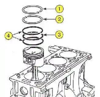
The location of the piston rings is shown in Figure 3.
The dimensions of the piston rings are given in the table 2.
- Thickness of the upper compression ring - 1.470-1.490 mm - gap in the lock - 0.15-0.30 mm;
- Thickness of the lower compression ring - 1.470-1.495 mm - gap in the lock - 0.40-0.60 mm;
- Thickness of the oil scraper ring expander - 1.470-1.530 mm - gap in the lock - 0.20-0.90 mm;
- Thickness of the oil scraper ring disc - 0.420-0.449 mm - gap in the lock - 0.20-0.90 mm
Ring wear along the perimeter is difficult to measure, so the gap in the lock is measured rings.
This gap ensures normal expansion of the ring when it is heated together with the engine, so it is in no case equal to zero on a cold engine.
When the ring wears around the perimeter, this gap increases, which is checked by measurement.

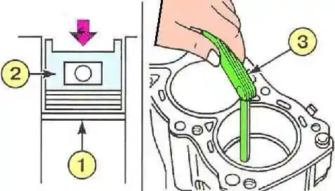
Install the piston ring (1) into the cylinder (see Fig. 4).
Advance the piston ring (1) to the middle of the cylinder using an inverted piston (2).
Measure the ring gap in the lock with a set of feeler gauges (3).
Replace the piston rings if the gaps are outside the tolerance; if the gaps remain outside the tolerance and with new rings (see Table 2), replace the cylinder block.
Checking the piston ring gap in the piston grooves
Thoroughly clean both the rings and the piston grooves from resins, otherwise the measurement will be inaccurate.

Use flat feeler gauges to check the gaps between the piston grooves and the piston rings (see Fig. 5).
The gap for the upper compression ring should be within 0.04-0.08 mm.
The gap for the lower compression ring should be within 0.025-0.07 mm.
The gap for the oil scraper ring should be within 0.08-0.22 mm.
If the gap values are outside the specified limits, replace the piston rings or the piston with the piston pin and rings.


