


Inspection and repair of the Cummins ISF2.8 engine cylinder block
We carry out the cylinder block inspection during a major engine overhaul.
The inspection and measurement of the block are carried out to assess the possibility of its reuse.
The engine cylinders are made as one piece, without the use of liners.
Important: in the event of damage or wear, the cylinders are not repaired.
Before removing the pistons assembled with the connecting rods, we measure the protrusion of each piston.
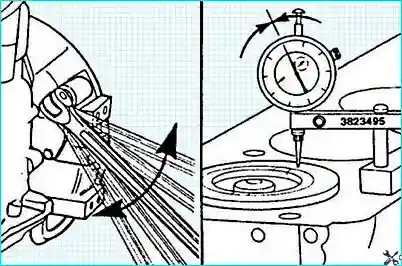
By measuring the piston protrusion it is possible to determine whether the upper surface of the cylinder block can be ground, if required.
We remove the engine as specified in the article — Removal and installation of the Cummins ISF2.8 engine.
We strip the engine.
Initial inspection
Before cleaning or further dismantling the cylinder block, we inspect it, checking for the absence of damage (cracks, scuff marks, etc.) that could rule out the possibility of its reuse.
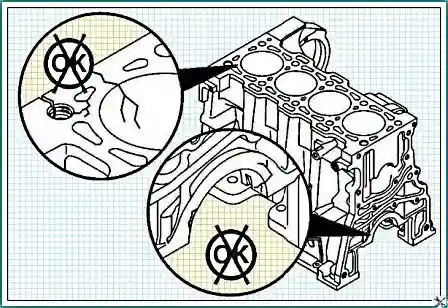
We pay particular attention to the following items:
- main bearing caps and seats;
- cylinders;
- upper face of the cylinder block;
- water pump inlet mounting surface;
- gasket surfaces at the front and rear of the cylinder block.
Cleaning and checking the possibility of using the block
Check all core plugs for the absence of signs of damage or leaks.
If the cylinder block needs thorough cleaning before reuse due to a large amount of foreign particles or contamination, remove all relevant core plugs.
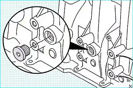
Make sure that all channels of the lubrication and cooling systems are clean.
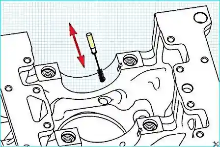
Using a non-metallic bristle brush and clean solvent, we clean the lubrication holes in the cylinder block.
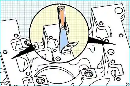
We thoroughly clean all sealing surfaces of the remains of the old gasket.
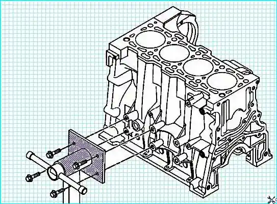
We remove the block from the stand.
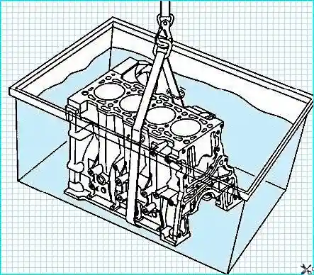
We clean the cylinder block in a washing tank.
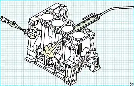
We take the cylinder block out of the washing tank. We clean the cylinder block with steam and dry it with compressed air.
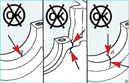
After cleaning the cylinder block, re-check it for the absence of signs of cracks, scuffing and discolouration that would rule out the possibility of its reuse.
To detect cracks, use a crack detection kit (catalogue number 3375432).
Pay particular attention to the following items:
- main bearing caps and seats;
- cylinders;
- upper face of the cylinder block;
- water pump inlet mounting surface;
- gasket surfaces at the front and rear of the cylinder block.
Check all threaded bolt holes for the absence of thread damage.
Threaded inserts may be used to repair threaded holes.
The following repair insert kits are provided:
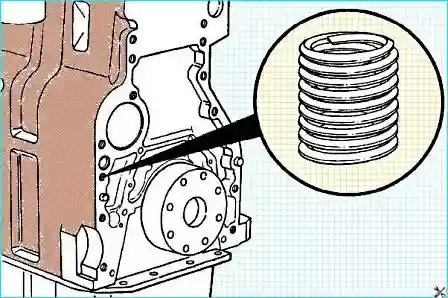
- catalogue number 3377905 — for American standard threads;
- catalogue number 3377903 — for metric threads.
Important: threaded inserts must not be used to repair the threaded holes for the main bearing cap bolts. If these are damaged, the cylinder block must be replaced.
Check the cylinder surface for the absence of glazed areas.
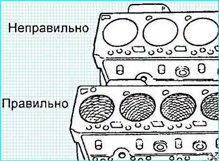
Crossed lines running at an angle of 20–25 degrees to the upper face of the cylinder block should be visible on the cylinder surface.
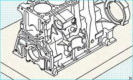
All cylinder block measurements must be carried out with the block lying on a flat surface with the main bearing caps fitted.
Important: if the cylinder block is on the stand and/or the main bearing caps are not fitted, the measurements may be inaccurate due to distortion (this applies to the cylinder diameters, main bearing bores, etc.).
We fit the main bearing caps without shells. We tighten the main bearing bolts.
Tightening torque — 80 N·m.
Main bearing seat diameter:
- journals 1 and 5 — 79.982–80.008 mm;
- journals 2, 3 and 4 — 79.977–80.013 mm.
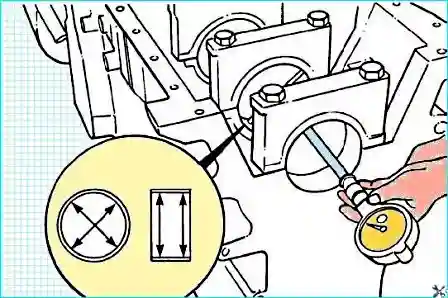
If the main bearing seat diameters do not meet the specification, check that the main bearing caps are correctly fitted and oriented.
If the main bearing caps are correctly fitted, the cylinder block must be replaced.
We measure the length of the main bearing bolts for possible reuse during assembly.
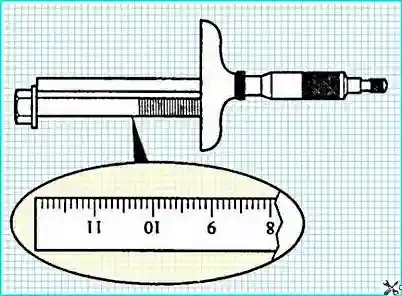
The main bearing bolt shank length must not exceed 119.25 mm.
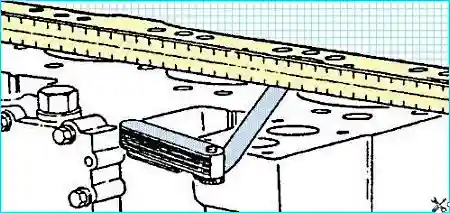
Check the flatness of the cylinder block using a precision straightedge and a feeler gauge.
Maximum out-of-flatness: 0.075–0.010 mm within a zone of 50 mm radius.
Check for the absence of minor irregularities or defects. If present, the upper surface of the cylinder block must be ground.
Important: grinding of the upper surface of the cylinder block is permitted only if the required piston protrusion height can be ensured afterwards.
The use of repair gaskets after grinding the upper surface of the cylinder block is not provided for.
If the required piston protrusion height cannot be ensured after such grinding, the cylinder block must be replaced.
The cylinder diameter is measured at a distance of more than 50 mm from the upper surface of the cylinder block in order to avoid a reduction in measurement accuracy.
Important: when carrying out measurements, matting or boring of the cylinders, all main bearing caps must be secured with bolts tightened to the required tightening torque.
Check the cylinder surface for the absence of damage or excessive wear.
Using a dial bore gauge (catalogue number 3376619), measure the cylinder diameter at 4 points spaced 90 degrees apart, at the extreme positions of the piston stroke.
- Bore diameter: 93.99–94.01 mm;
- Out-of-roundness: 0.01 mm;
- Taper: 0.01 mm.
Block repair
Before repairing the cylinders, the oil galleries and tappet holes in the upper part of the cylinder block must be closed off with water-resistant tape.
Cylinder surface matting:
Matting provides the surface quality required for the normal operation of the piston rings.
Matting is permitted only when the cylinder dimensions still meet the specification.
The seating of new piston rings in glazed cylinders will not be tight.
Use a round honing head (No. 3823612 according to the catalogue) or similar at a speed of 300–400 rpm, performing one vertical stroke cycle per second.
Use high-quality honing oil or a mixture of different proportions of SAE 30W and diesel fuel.
The vertical strokes must be smooth and continuous over the entire height of the cylinder.
Check the cylinder bore after 10 strokes.
The angle of the crossed lines depends on the rotational speed and the speed of vertical movement of the honing head.
Too high or too low a movement speed will cause this angle to deviate from the specification.
On a correctly matted cylinder surface, crossed lines running at an angle of 20–25 degrees to the upper face of the cylinder block should be visible.
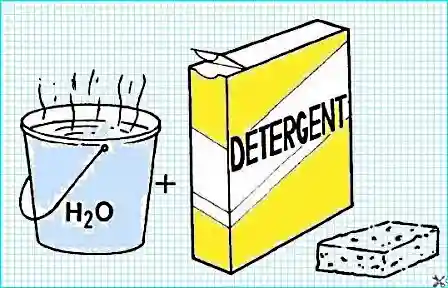
To remove the glaze, use a concentrated detergent solution in hot water to wash the cylinders.
Important: carry out the cylinder cleaning immediately after matting. Failure to comply with this requirement may result in engine failure.
Wash the cylinders until the cleaning agent is completely removed.
Dry the cylinder block with compressed air.
Check the cleanliness of the cylinder surface by wiping it with a piece of white lint-free cloth slightly moistened with oil.
If abrasive material remains, continue cleaning until it is completely removed.
Wash the cylinder surface with solvent. Dry the cylinder block with compressed air.
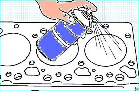
When replacing the cylinder block or using a cylinder block that has been in storage, be sure to remove the engine oil and preservation oil from the cylinder surfaces, gasket seats and main bearing seats before using it.


