
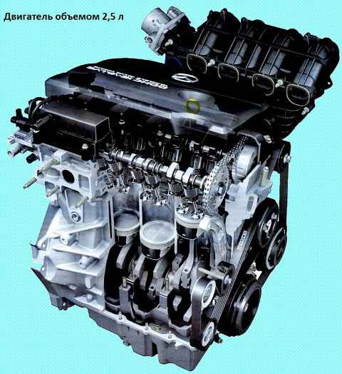
For Mazda 6 cars for the Russian market, transverse four-stroke gasoline engines with in-line vertical arrangement of cylinders with a volume of 1.8 liters (120 hp), 2.0 liters (147 hp) and 2.5 liters are installed (170 hp) liquid-cooled
Engines with overhead two-way camshafts have four valves per cylinder
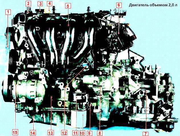
1 - auxiliary drive belt; 2 - electromagnetic valve of the phase regulator; 3 - oil filler cap; 4 - oil level dipstick; 5 - intake manifold; 6 - throttle assembly; 7 - gearbox; 8 - starter; 9 - oil pressure sensor; 10 - oil filter; 11 - oil cooler; 12 - absolute pressure sensor; 13 - cylinder block; 14 - oil sump; 15 - air conditioning compressor
The camshafts of the engines are driven by a lamellar chain, the tension of which is provided by an automatic tensioner
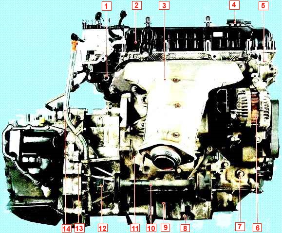
Engine with a volume of 2.0 liters (rear view): 1 - coolant temperature sensor; 2 - cylinder head cover; 3 - exhaust manifold; 4 - oil filler cap; 5 - cylinder head; 6 - generator; 7 - plug hole of the fixing bolt; 8 - drain plug; 9 - oil sump; 10 - intermediate shaft; 11 - cylinder block; 12 - speed sensor; 13 - gearbox; 14 - automatic transmission fluid level probe
On all engines, the valves are driven directly from the camshafts through cylindrical tappets, which simultaneously serve as adjusting elements for clearances in the valve drive.
The cylinder head is made of aluminum alloy according to the transverse cylinder scavenging pattern (inlet and outlet channels are located on opposite sides of the head).
Saddles and valve guides are pressed into the head
The intake and exhaust valves are equipped with one spring each, fixed through the plate with two crackers. The head of the block is centered on the block with two bushings and attached to the block with ten bolts
A non-shrink metal-reinforced gasket is installed between the block and the head. In the upper part of the cylinder head, there are five bearing supports for two camshafts
The lower parts of the supports are made in one piece with the cylinder head, and the upper parts (covers) are bolted to the head.
The support holes are processed together with the covers, so the covers are not interchangeable, each of them has a serial number
On the 2.0 and 2.5 liter variable valve timing engines, the function of the front bearings is performed by the caliper of the dynamic valve timing system, which at the same time keeps the camshafts from axial displacement.
The cylinder block is a single casting of special ductile iron that forms the cylinders, the cooling jacket, the upper part of the crankcase and five crankshaft bearings, made in the form of crankcase baffles
The cylinders are bored directly into the body of the block. In the lower part of the block there are five beds of main bearings with removable covers bolted to the block.
The main bearing caps are machined complete with the block and are not interchangeable
In the bearing beds (in the upper parts of the bearings) there are oil outlets for lubricating the main bearings, and through holes into which ball valves with nozzles are pressed, through which oil is sprayed onto the piston bottoms and cylinder walls.
The cylinder block has special lugs, flanges and holes for attaching parts, components and assemblies, as well as channels of the main oil line.
A crankshaft made of ductile iron rotates in main bearings equipped with thin-walled steel liners with an anti-friction layer
Upper liners installed in the cylinder block have a groove on the inner surface and a through slot through which oil flows from the outlet of the oil channel to the ball valve with a nozzle
There are no grooves or slots in the bottom liners.
The axial movement of the crankshaft is limited by two identical thrust plates rings made in one piece with the middle main bearing shell.
A flywheel is attached to the rear end of the crankshaft with six bolts.
At the front end of the crankshaft is a timing sprocket and an accessory drive pulley.
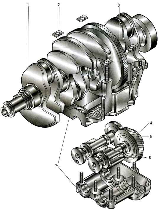
Crankshaft with balancing shafts for a 2.5-liter engine: 1 - crankshaft; 2 - spacers; 3 - balancing gear of the crankshaft; 4 - drive gears of balancing shafts; 5 - intermediate gear; 6 - balancing shafts; 7 - body of balancing shafts
The 2.5 liter engine is equipped with balancing shafts 6 (fig.) made of cast iron. The shafts are installed in housing 7, fixed at the bottom of the cylinder block.
The balancing shafts are connected to each other by helical gears and are driven from the crankshaft gear mounted in place of the counterweight.
Balancing shafts serve to reduce the inertial forces of vertical oscillations caused by the movement of parts of the crank mechanism.
Short skirted pistons are made of aluminum alloy

On the cylindrical surface of the piston head there are annular grooves for the oil scraper and two compression rings
Six holes in the oil scraper ring groove are designed to drain the oil removed by the ring from the cylinder walls. Two of these holes bring oil to the piston pin.
Tubular cross-section piston pins are installed in the piston bosses with a gap and are pressed with an interference fit into the upper heads of the connecting rods, which are connected with their lower heads to the connecting rod journals of the crankshaft through thin-walled liners, the design of which is similar to the main liners

Steel forged connecting rods with an I-section shank. Connecting rods are processed complete with covers.
In order not to confuse them during assembly, the cylinder serial number is marked on the side surfaces of the connecting rods and caps.
Camshafts are cast, cast iron.
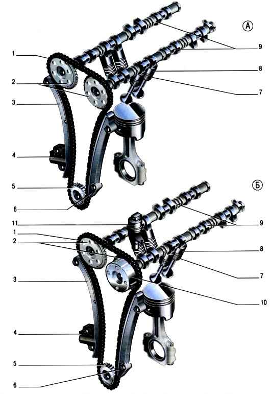
Gas distribution mechanism: A - gas distribution mechanism of 1.8 l engines; B - gas distribution mechanism of 2.0 and 2.5 liter engines; 1 - chain; 2 - camshaft sprockets; 3 - chain tensioner shoe; 4 - chain tensioner; 5 - crankshaft gear; 6 - chain damper; 7 - valve; 8 - valve pusher; 9 - camshafts; 10 - mechanism for adjusting the position of the intake camshaft; 11 - phase regulator solenoid valve
The gas distribution mechanism (fig.) is closed with a plastic cylinder head cover. It has an oil separator of the crankcase ventilation system.
Combined lubrication system

The oil sump, cast from aluminum alloy, is attached to the bottom of the cylinder block. The oil sump flange is sealed with a sealant-gasket. The crankcase has an oil drain hole closed with a screw plug.
The oil filter is full-flow, non-separable (as an option, a collapsible oil filter with a replaceable filter element made of porous paper can be installed), with bypass and anti-drain valves.
The crankcase ventilation system is closed, forced, with the removal of crankcase gases through the oil separator into the air filter cavity.
The engine cooling system is sealed, with an expansion tank
The engine power supply system consists of an electric fuel pump installed in the fuel tank, a throttle assembly, a fine fuel filter and a fuel pressure regulator installed in the fuel pump module, a fuel pressure pulsation compensator, injectors and fuel pipelines, and also includes air filter.
The exhaust gas recirculation system with a recirculation valve driven by a stepper motor, at the signals of the electronic unit of the engine control system, bypasses part of the exhaust gases into the intake pipe.
This achieves a reduction in the toxicity of car emissions and compliance with modern environmental standards.
The ignition system is microprocessor-based and consists of individual ignition coils and spark plugs.
The ignition coils are controlled by the electronic engine control unit. The ignition system during operation does not require maintenance and adjustment.
The engine management system includes an electronic control unit (controller), temperature and absolute pressure sensors in the intake pipe, throttle position, coolant temperature, crankshaft position, camshaft position, outside air temperature, oxygen concentration (control and diagnostic), the position of the accelerator pedal, brake and clutch, detonation, as well as actuators, connectors and fuses.
The power unit (engine with gearbox, clutch and final drive) is mounted on three supports with elastic rubber elements: two front ones, which take the bulk of the power unit. and rear, compensating for torque from the transmission and the load that occurs when starting the car from a stop, accelerating and braking.
Variable valve timing system for 2.0 and 2.5L engines
This system allows you to set the optimal valve timing for each moment of engine operation, which, in turn, achieves increased power, better fuel efficiency and less exhaust toxicity.
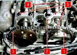
Elements of the phase regulator system for 2.0 and 2.5 liter engines: 1 - mechanism for adjusting the position of the intake camshaft; 2 - electromagnetic valve of the phase regulator; 3 - timing chain; 4 - intake camshaft; 5 - camshaft bearing caps
The valve timing mechanism installed on the intake camshaft, at the signal of the electronic engine control unit, rotates the shaft to the required angle in accordance with the engine operating mode.
The valve timing mechanism is a hydraulic mechanism connected to the engine lubrication system.
Oil from the engine lubrication system enters the gas distribution mechanism through channels
Rotor 2 turns the camshaft at the command of the engine control unit.
To determine the instantaneous position of the camshaft, a camshaft position sensor is installed at the rear of the camshaft.
The position sensor ring is located on the camshaft journal.
A caliper 5 of the VCT system is installed on the front of the cylinder head, which simultaneously functions as front bearing caps and a holder for camshaft oil seals.
A solenoid valve is mounted on the cylinder head, which hydraulically controls the mechanism.
The solenoid valve, in turn, is controlled by the electronic engine control unit.
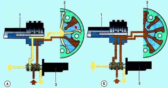
The process of changing the valve timing: A - setting the intake camshaft to the early opening position of the gas distribution valves; B - setting the intake camshaft to the position of the late opening of the gas distribution valves; 1 - camshaft; 2 - mechanism for changing the valve timing; 3 - solenoid valve of the phase regulator system
The use of the VCT mechanism provides a smooth change in the angle of the intake camshaft to the positions of early and late opening of the gas distribution valves
The control unit determines the position of the intake camshaft from the signals of the phase sensor and the crankshaft position sensor and issues a command to change the position of the shaft
In accordance with this command, the spool of the solenoid valve is moved, for example, in the direction of greater advance of the opening of the intake valves new
This forces pressurized oil through a channel in the timing case into the VCT case and causes the camshaft to rotate in the desired direction.
When the spool is moved in the direction corresponding to the earlier opening of the valves, the channel for their later opening is automatically connected to the drain channel.
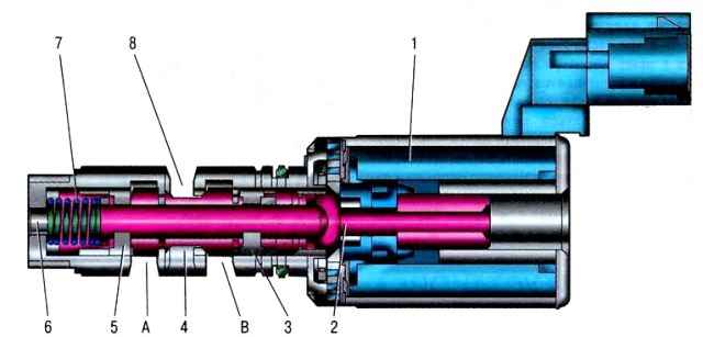
The solenoid valve of the phase regulator of engines with a volume of 2.0 and 2.5 liters: 1 - electromagnet; 2 - valve spool; 3 - an annular groove connected by a channel in the cylinder head cover with the second working chamber of the phase regulator; 4 - annular groove for oil drainage; 5 - annular groove connected to the channel in the cylinder head cover with the first working chamber of the mechanism for changing the valve timing; 6 - hole for supplying oil from the main line; 7 - valve spring; 8 - hole for draining oil; A - a cavity connected by a channel in the cylinder head cover with the first working chamber of the phase regulator fluid coupling; B - a cavity connected by a channel in the cylinder head cover with the second working chamber of the variable valve timing mechanism
If the camshaft has rotated to the required angle, the solenoid valve spool, at the command of the control unit, is set to a position in which oil is maintained under pressure on both sides of each of the clutch rotor blades
If it is required to turn the camshaft towards a later opening of the valves, the control process is carried out with oil supply in the opposite direction.
The components of the VCT system (solenoid valves and dynamic camshaft positioners) are precision-manufactured assemblies
In this regard, when performing maintenance or repair of the variable valve timing system, only the replacement of the complete system elements is allowed.
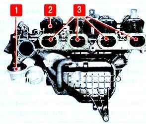
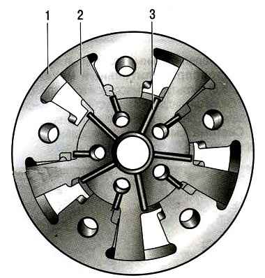
The intake manifold is plastic, with variable geometry and additional swirl flaps 3 at the inlet to each cylinder.
When the engine is running at low load, the swirl flaps are closed and create a swirl of the air-fuel mixture entering the cylinder, which contributes to more complete combustion of the fuel
This reduces fuel consumption and exhaust emissions.
When the load increases, the swirl flaps open under the action of vacuum supplied to the drive 1 of the flaps through a solenoid valve controlled by the engine electronics
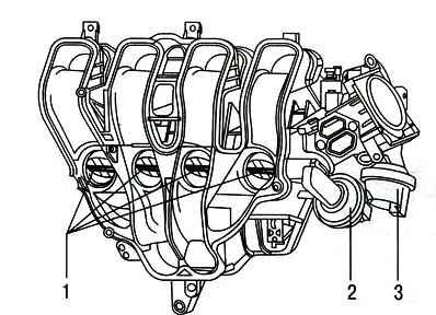
Next to the swirl flap control valve on the cylinder head, there is a solenoid valve for controlling the length of the intake manifold passages.
Via this valve, vacuum is supplied to the actuator of 2 dampers, which change the length of the intake manifold channels depending on the engine speed. When the engine is not running, dampers 1 are open
When the engine is started, the dampers close under the action of vacuum and remain closed until the engine speed exceeds 4500 min-1 - the length of the intake manifold channels is minimal
If the speed rises above the specified value, the dampers open at the command of the electronic engine control unit, as a result of which additional volume is connected to the intake manifold channels.
Management of the length of the intake manifold channels allows you to improve the filling of the cylinders with air through the use of resonant boost, as a result of which the engine's power and fuel efficiency are improved
Possible engine malfunctions, their causes and remedies
Engine won't start
- no fuel pressure in the rail:
Clogged fuel lines - flush and blow out the fuel tank and fuel lines;
Clogged fuel filter - replace;
Fuel pump defective - replace;
Fuel pressure regulator defective - replace;
Faulty ignition system - see engine management system;
Faulty sensors crankshaft position - replace.
Engine runs erratically or stalls at idle:
Insufficient pressure in the fuel rail - see fault "Engine does not start";
The throttle position sensor is faulty or the throttle assembly is dirty - replace the throttle assembly or flush the throttle body;
Air leakage through the crankcase ventilation hoses and the hose connecting the intake manifold to the vacuum brake booster - tighten the fastening clamps, replace damaged hoses
The system for changing the valve timing is faulty - it is necessary to diagnose and repair the system
The engine does not develop full power and is not throttled enough:
Incomplete throttle opening - flush the throttle body or replace the throttle body
Faulty throttle position sensor - replace throttle body
Insufficient fuel pressure in the fuel rail - see "Engine won't start" fault
Air filter dirty - replace the filter element How to replace Mazda 6 air filter element
Faulty ignition system - see "Engine Management System"
Clearances in the valve drive mechanism are broken - adjust the clearances How to adjust the clearances Mazda 6 engine valves
Insufficient compression (below 1 MPa (10 kgf/cm2)):
- - broken cylinder head gasket - replace the gasket;
- - burnout of pistons, breakage or occurrence of piston rings - clean rings and grooves of pistons from carbon deposits, replace damaged rings and piston;
- - poor fit of valves to seats - replace damaged valves, grind seats;
- - excessive wear of cylinders and piston rings - replace pistons, bore and honing cylinders;
The system for changing the valve timing is faulty - it is necessary to diagnose and repair the system
Insufficient oil pressure in a warm engine
- using the wrong brand of oil
Change the recommended oil
- dilution or foaming of the oil due to the penetration of fuel or coolant into the oil sump
Remove causes of fuel or coolant intrusion. Change oil
- pollution of the working cavity or wear of the oil pump
Flush or repair the oil pump
- clogged oil filter
Change the oil filter
- loosening or clogging of the oil receiver
Fix the oil receiver, wash its filter
- increased clearance between the main or connecting rod bearing shells and the crankshaft journals
Sand the necks and replace the liners
- cracks, pores in the walls of the oil channels of the cylinder block or clogging of the oil lines
Repair the cylinder block. If it is impossible to eliminate the defect, replace the block
- loose installation of oil channel plugs or their absence
Restore the tightness of the plugs, install the missing plugs
Increased oil consumption
- oil leakage through the engine seals
Tighten fasteners or replace gaskets and seals
- the crankcase ventilation system is clogged
Clean the parts of the crankcase ventilation system How to clean the ventilation system engine crankcase Mazda 6
- wear of piston rings or engine cylinders
Rebore cylinders and replace pistons and rings
- breakage of piston rings
Replace rings
- coking of oil scraper rings or grooves in piston grooves
Clean the rings and grooves from soot, change the engine oil
- wear or damage to valve stem seals
Replace valve stem seals Replacement of Mazda 6 engine valve stem seals
- increased wear of valve stems or guide bushings
Replace valves, repair cylinder head
Knock of crankshaft main bearings
Usually a dull, metallic sound.
Knocking is detected when the throttle valves are suddenly opened at idle. Its frequency increases with an increase in the frequency of rotation of the crankshaft.
Excessive axial clearance of the crankshaft causes a sharper knock, with uneven intervals, especially noticeable when the crankshaft speed is gradually increased or decreased of that shaft
- insufficient oil pressure
See fault "Insufficient oil pressure on a warm engine"
- loosened flywheel mounting bolts
Tighten the bolts to the recommended torque Removing and installing the Mazda 6 engine flywheel
- increased clearance between journals and main bearing shells
Sand the necks and replace the liners
- increased clearance in the crankshaft thrust bearing
Replace thrust washers, check clearance
Rattle of connecting rod bearings
Usually, the knock of the connecting rod bearings is sharper than the knock of the main bearings. It is heard at idle speed of the engine with a sharp opening of the throttle. The place of knocking is easy to determine by turning off the spark plugs in turn
- insufficient oil pressure
See fault "Insufficient oil pressure on a warm engine"
- excessive clearance between piston rings and grooves on the piston
Replace rings or pistons with rings
Increased gas distribution noise
- increased clearances in the valve drive mechanism
Adjust the valve clearances How to adjust the valve clearances of a Mazda 6 engine
- broken valve spring
Replace the spring
- excessive clearance between valve stem and guide sleeve
Replace valve and guide sleeve
- wear of camshaft cams
Replace camshafts
Knocking on a cold engine, heard for 2-3 minutes after starting and increasing with increasing engine speed
- increased clearance between pistons and cylinders
Piston knocking that disappears after the engine warms up is not a sign of a malfunction. With constant knocking, replace the pistons, bore and hone the cylinders
- loosening of the crankshaft pulley
Tighten the mount
Short-term knocks immediately after starting the engine
- using the wrong brand of oil
Change the oil
- increased axial clearance of the crankshaft
Replace the middle main bearing thrust washers
- increased clearance in the front main bearing
Replace front main bearing shells
Knocking in a warm engine at idle
- weakening or wear of the auxiliary drive belt
Change the belt
- increased clearances between piston pins and holes in piston bosses
Replace pistons and pins
- noise of parts of the gas distribution mechanism
We look at the malfunction "Increased noise of the gas distribution mechanism"
- use of substandard oil
Change the oil
- increased clearance between the connecting rod journals of the crankshaft and liners
Replace the liners and sand the necks
- the axes of the upper and lower connecting rod heads are not parallel
Replace connecting rod
Strong knocks in a warm engine when the crankshaft speed is increased
- breakage of the crankshaft pulley hub
Replace damaged parts
- cracks or breaks in the accessory belt
Replace damaged belt
- the flywheel is loose Removing and installing the flywheel of the Mazda 6 engine
Tighten the flywheel mounting bolts
- an excessive increase in the gaps between the shells of the connecting rod and main bearings of the crankshaft
Regrind the necks to repair size and replace the liners
Increased engine vibration
- crankshaft imbalance
Remove and balance the crankshaft
- pistons of different masses are installed
Disassemble the connecting rod and piston group, select pistons by weight
- unequal gaps in the valve drive mechanism
Adjust gaps
- unequal compression values in cylinders
Check compression and replace defective parts
- Powertrain suspension mount pads are badly worn or hardened How to replace Mazda 6 powertrain mounts
Replace supports
- the crankshaft pulley or accessory pulleys are loose
Tighten the mount
Engine overheating
- insufficient amount of liquid in the cooling system
Add coolant to the cooling system
- the outer surface of the radiator is heavily soiled
Clean the outer radiator surface with water jet
- the thermostat is faulty
Replace thermostat
- the electric fan of the cooling system is faulty
Check fan motor, replace defective parts
- the expansion tank plug valve is faulty (constantly open, due to which the system is under atmospheric pressure)
Replace expansion tank cap
- use of gasoline with a lower octane rating
Fill with qualified gasoline
- damaged cylinder head gasket
Replace gasket
With a certain skill and care, many malfunctions of the engine and its systems can be quite accurately determined by the color of the smoke coming out of the exhaust pipe. Blue smoke indicates that oil has entered the combustion chambers, and constant smoking is a sign of severe wear of the parts of the cylinder-piston group. The appearance of smoke during regassing, after prolonged cranking by the starter, after long idling or immediately after engine braking, as a rule, indicates wear on the valve stem seals. Black smoke is a sign of too rich a mixture due to a malfunction of the engine control system or injectors. Blue or thick white smoke with an admixture of moisture (especially after the engine has overheated) means that the coolant entered the combustion chamber through a damaged cylinder head gasket. If this gasket is severely damaged, the liquid sometimes enters the oil sump, the oil level rises sharply, and the oil itself turns into a cloudy whitish emulsion. White smoke (steam) when the engine is cold in wet or cold weather is normal.
It is quite common to see a car standing in the middle of a city traffic jam with an open hood, emitting puffs of steam. Overheat. It is better, of course, not to allow this, often looking at the temperature gauge. But no one is immune from the fact that the thermostat, electric fan may suddenly fail, or coolant will simply flow. If you miss the moment of overheating, do not panic and do not aggravate the situation. Overheating is not as bad as its possible consequences. Never immediately turn off the engine: it will get a heat stroke and, possibly, having cooled down, will refuse to start at all. Having stopped, let it idle, while the fluid circulation will remain in the system. Turn on the heater to maximum power and open the hood. If possible, pour cold water over the radiator. Stop the engine only when the temperature has dropped. But never immediately open the cork of the expansion tank - on an overheated engine, a geyser from under the open cork is provided to you. Take your time, let everything cool down, so you save the health of the machine and your own health.
Almost all instructions for the car contain a recommendation to depress the clutch when starting the engine. This recommendation is justified only in case of starting in severe frost, so as not to waste battery energy on turning the shafts and gears of the gearbox in thickened oil. In other cases, this measure is aimed only at ensuring that the car does not move if the gear is switched on due to forgetfulness. Such a technique is harmful to the engine, since when the clutch is depressed, a significant force is transmitted through it to the thrust bearing of the crankshaft, and during start-up (especially cold), lubrication is not supplied to it for a long time. The bearing wears out quickly, the crankshaft receives axial play, starting off begins to be accompanied by strong vibration. In order not to spoil the engine, make it a habit to check the position of the gear lever before starting and start the engine with the parking brake applied, without depressing the clutch unless absolutely necessary

")
")
")
")
")
")
")
")