The front suspension of the car is independent, spring, lever (with transverse levers), with double-acting hydraulic single-tube shock absorbers.
The front suspension is a unit consisting of the following main parts: crossbar 3, steering knuckles 6, lower 13 and upper 4 levers, springs 10, shock absorbers 11, stabilizer.
The suspension assembly also includes the front wheel hubs with bearings and brake discs.
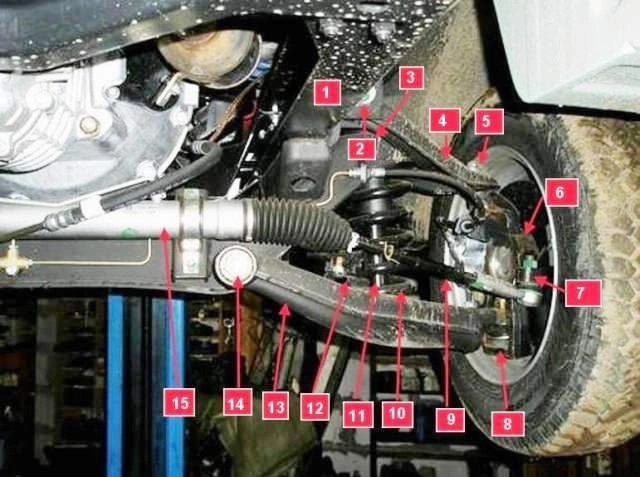
The front suspension, combined with the steering gear 15 and steering rods 9, is an independent unit assembled on a removable cross member.
The crossbar, in turn, is bolted to the vertical and lower horizontal shelves of the side members of frame 1 of the car.
The steering knuckle of the front suspension is connected to the upper and lower arms by ball joints 5 and 8.
A front brake shield and a hub assembly are attached to the fist, consisting of a hub with a brake disc, pressed into a double-row tapered bearing and fixed in it with a central bolt with a thrust ring.
Double-row sealed tapered roller bearing is grease lubricated and requires no adjustment or relubrication during its lifetime.
Ball joints of non-separable design. They do not require adjustment and relubrication during the entire service life.
The upper arm is stamped, with welded eyelets for silent blocks.
The upper arm is attached to the cross member brackets with two adjusting bolts through eccentric washers.
The lower arm is stamped welded, with welded eyelets for silent blocks.
The lower arm is attached to the crossmember bracket through silent blocks with a through axle with two nuts.
Suspension springs are cylindrical with unpolished support coils.
Through rubber gaskets, the springs are supported by the upper ends in the cups of the cross member, and by the lower ends - in the cups of the lower levers.
Shock absorbers are telescopic, hydraulic, with gas boost, double-acting. Installed inside suspension springs.
A rubber-metal hinge is pressed into the lower eye of the shock absorber, the axis of which is attached to the spring cup of the lower arm with two bolts.
The upper end of the shock absorber rod is attached through rubber pads to the suspension cross member.
A rebound buffer is integrated inside the shock body, and a compression stroke buffer is put on the stem.
Protruding from the shock absorber, the upper part of the rod is protected from dirt by a rubber cap.
An anti-roll bar is used to reduce roll in corners and improve handling.
The middle part of the stabilizer bar is stapled through rubber bushings to the suspension cross member.
The ends of the rod are also connected to the lower arms with brackets through rubber bushings.
Possible malfunctions of the front suspension and methods of elimination
Cause of malfunction (Remedy)
Knocking in the front suspension:
- Loose suspension parts
Tighten screw connections
- Wear of stabilizer bushings
Replace defective bushings
- Shock absorber loosening
Tighten the bindings
- Wear of the lower hinge of the front shock absorber
Replace shock absorber
Reducing the effectiveness of the shock absorber:
- Violation of wheel alignment angles
Adjust the angles of the front wheels (article - Adjusting the angles of the front wheels GAZelle Next)
- Increased play of the front wheel bearings
Replace the bearings (article - Replacing the front wheel hub bearing GAZelle Next)
- Decreased efficiency of shock absorbers
Replace shock absorbers
- Wheels not balanced
Balance the wheels
- Worn silent blocks of front suspension arms
Replace lever assemblies or silent blocks
Hard bumps in the suspension on rough roads:
- suspension or breakage of the coils of the suspension spring
Replace the spring
- Reduced efficiency of shock absorbers
Replace shock absorbers
- Loss of elasticity or destruction of the compression stroke buffer
Replace the compression buffer on the damper rod
Suspension creaking on road bumps
- Worn silent blocks of suspension arms
Replace lever assemblies or bushings
Checking the front suspension
Make sure the suspension parts are not cracked or rubbing against road obstacles.

Checking the condition of the metal hinges of the upper arms
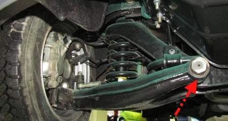
Checking the condition of the lower arms
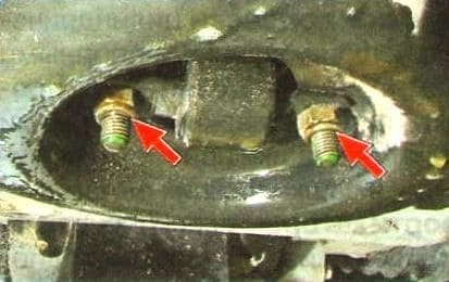
Inspecting the hinges of the lower shock absorber mount
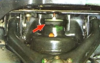
Inspecting the rubber bushings of the upper shock absorber mount
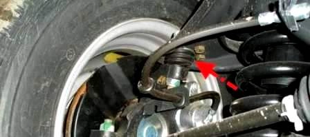
Checking the condition of the protective covers of the upper ball joints
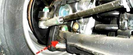
Checking the condition of the lower ball joints
If the covers are damaged, we replace the ball joints.
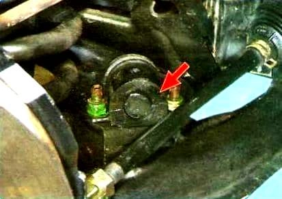
Check the condition of the rubber bushings and the fastening of the stabilizer bar brackets to the levers
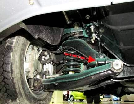
Check the condition of the rubber bushings and the fastening of the stabilizer bar brackets to the suspension cross member
On rubber parts and rubber-metal suspension joints (silent blocks) are not allowed:
- - signs of aging, cracks, one-sided bulging of the rubber mass;
- —removal of the rubber mass from the armature.
Replace defective parts.
Checking shock absorbers
According to Mando Corporation shock absorber repair documentation, a shock absorber is considered defective if more than half of its body is covered by leaking oil.
Check ball joints for play.
To do this, lift the front of the car until the wheel is off the ground.
Place a support under the lower control arm in the pivot area and lightly load the spring.
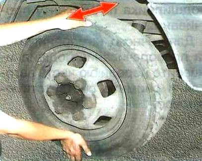
Swing the wheel vertically.
If play is felt when the wheel wobbles, replace the worn ball joint.
When jiggling the suspended front wheel, it is difficult to distinguish play in the hub bearing from play in the ball joints.
Ask an assistant to press the brake pedal: if in this case you feel play, then the ball joints are faulty. Article - Replacing GAZelle Next front suspension ball joints
If the ball joints are in good condition, while shaking the wheels in a vertical plane, make sure that there are no play in the hub bearings.
If there are signs of backlash a, do an accurate bearing test.
In order to accurately measure the amount of backlash, attach a dial indicator to the suspension parts (for example, on the upper arm).
Place the tip of the indicator on the surface of the brake disc at a diameter of 200 mm.
Fix the arm with a shoulder of 500 mm on the wheel studs.
Swing the lever in the axial direction with a force of about 30 kgf.
Maximum lateral movement of the disc surface due to bearing play! should not exceed 0.050 mm.
For larger displacement, replace the bearing (article - Replacing the front wheel hub bearing wheels GAZelle Next).
Another important criterion for evaluating the condition of a hub bearing is wheel rolling noise.
You can check the bearing for noise with a stethoscope by turning the suspended wheel manually.
The hub must rotate silently! without jamming, evenly.
Clicks or hums may indicate worn raceways and rollers.
If the result of the check is in doubt, the bearing preload must be checked by turning torque.
To accurately measure the torque of the bearing, hang the front of the car and remove the corresponding wheel.
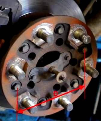
Measure the diameter D (in meters) of the circle formed by the centers of the wheel studs.
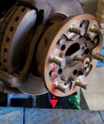
Fix a dynamometer on any wheel stud and pull it tangentially to the hub circumference (for example, in the direction of the arrow in the photo). Register the resulting force F.
Calculate the turning torque using the formula M = F x 1/2D.
If the torque exceeds 5 Nm, the bearing is defective and needs to be replaced
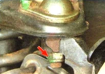
Checking the tightness of the threaded connections of the nuts of the fingers of the upper ball joints
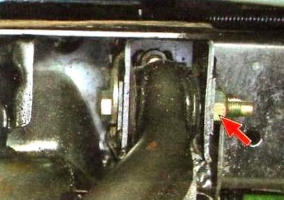
Checking the tightening of the adjusting bolts of the hinges of the upper arms

Checking the tightening of the nuts of the axes of the lower hinges
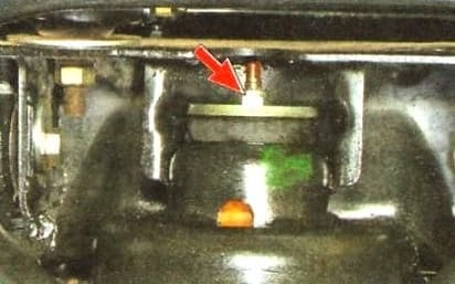
Checking the tightness of the shock absorber rod nuts
Checking the tightening torque and tightening threaded connections that are locked using an anaerobic thread locker is not allowed.
Stroking off the bolts (nuts) in this case leads to the destruction of the retainer layer and subsequent loosening of the connection.
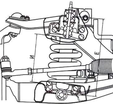
Checking the settlement of the suspension springs.
To do this, with the car standing on the ground, measure the distance “AND” between the subframe cross member and the lower suspension arm.
If "I" is less than 205 mm, the spring must be replaced (to carry out this measurement, you must first remove the shock absorber).


