


Adjusting the UAZ clutch linkage and mechanism
The clutch linkage is adjusted if the vehicle is fitted with a spring-and-lever clutch.
The diaphragm-spring clutch requires no adjustment of free play or of the release mechanism. The necessary travels and clearances are ensured by the design.
Tools and materials required
For the job you will need: a rule, 13 and 14 mm spanners, pliers, a screwdriver and rags.
Materials used: a new pushrod locknut if necessary, a gauge or three 9.5 mm thick washers, a plate (the flywheel can be used as the plate). The rule is used to check dimensions; threaded joints are locked with the locknuts after adjustment.
Adjusting the release linkage
Using the rule, measure the free play of the release linkage pedal, which must be within 35–55 mm for the spring-and-lever clutch and 5–30 mm for the diaphragm-spring clutch.
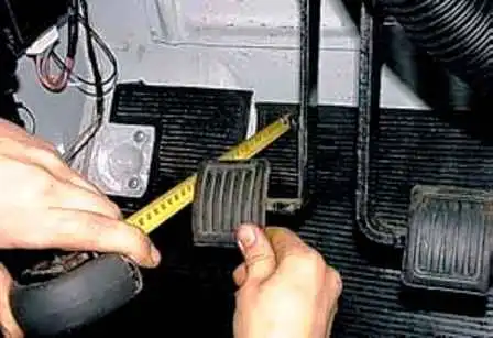
With the pedal pressed fully down, measure its total travel, which must be 185 mm for the spring-and-lever clutch and 165 mm for the diaphragm-spring clutch.
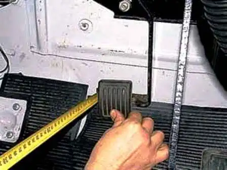
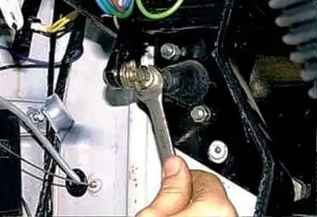
To change the pedal position, undo the locknut with a 13 mm spanner.
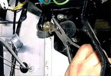
Turning the rod with pliers, set the required pedal position.
The distance from the engine bay bulkhead to the centre of the clutch master cylinder rod axis with the pedal released must be 96 mm.
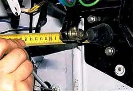
The free play of the lower end of the clutch release fork must be at least 17 mm. If necessary, it is adjusted by changing the length of the slave cylinder pushrod. To do this, after slackening the locknut, screw in or out the threaded part of the pushrod until the required value is obtained, then tighten the locknut.
Adjusting the position of the release levers
The clutch mechanism requires adjustment if the checked distance from the swivel head of the adjusting screws on the release levers to the plate of the fixture does not correspond to 51.5 ± 0.75 mm (see figure).
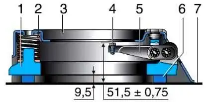
The distance to the head of each of the screws must not differ by more than 0.2 mm.
By screwing the adjusting screws in or out, set the required dimension and lock the lever screws by settling the lever edge into the slot of the screw shank.