
The car has three independent brake systems: working, spare and parking
The working brake system is hydraulic, dual-circuit (divided into front and rear circuits), with a vacuum booster, a pressure regulator and an emergency drop sensor in the brake fluid level in the reservoir
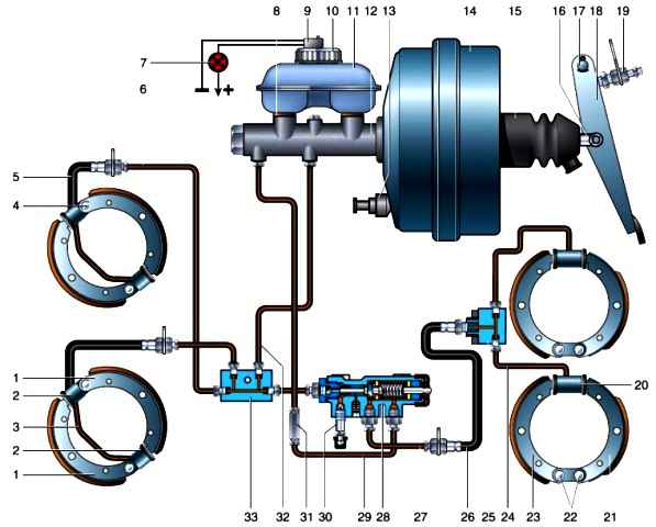
Brake system without signaling device: 1 - front wheel brake pads; 2 - brake cylinders of the front wheel; 3 - brake tube of the front wheel; 4 - brake shoe support pin; 5 - front wheel brake hose; 6, 24, 27, 20, 32 - brake pipes; 7 - signaling lamp for a drop in the level of brake fluid; 8 - rubber gasket; 9 - brake fluid level drop sensor; 10 - tank cover; 11 - tank; 12 - main brake cylinder; 13 - vacuum wire fitting with check valve; 14 - vacuum amplifier; 15 - protective cover; 16 - pusher; 17 - pedal axis; 18 - pedal; 10 - brake signal switch; 20 - rear wheel brake cylinder; 21.23 - rear and front brake pads of the rear wheel; 22 - brake pad support pins; 25 - tee; 25 - rear brake hose; 28 - pressure regulator; 30 - bleed valve of the regulator; 31 - coupling; 33 - splitter
A spare system is formed by each circuit of the working system.
If one of the circuits of the brake system fails, the second circuit provides braking of the car, albeit with less efficiency
The system nodes are connected by copper pipes and rubber hoses.
The brake mechanisms of the front wheels are drum, with two single-piston cylinders, each of which acts on its own shoe
The cylinders are interconnected by a copper tube
The gaps between the shoes and the drum are adjusted manually.
Each cylinder has an air bleed valve.
Brake mechanisms of the rear wheels - drum, with two-piston wheel cylinders and manual adjustment of the gap between the pads and the drum.
In the middle part of the brake shields of the front and rear wheels there are eccentrics for adjusting the position of the pads after they have been replaced or during operation
In addition, when replacing the pads, their position can be changed by turning the eccentric support pins.
The pads are connected to the pads with aluminum rivets
The minimum allowable thickness of the brake pads when they are worn is 0.5 mm from the working surface to the heads of the rivets.
Maximum allowable inside diameter of brake drums is 281mm
The rear brake pads on the rear wheels are shorter than those on the front.
This is necessary to ensure uniform wear of the linings.
The main brake cylinder with a two-section reservoir and an emergency drop in brake fluid level sensor is attached to the vacuum booster
Some vehicles have separate tanks for each system circuit.
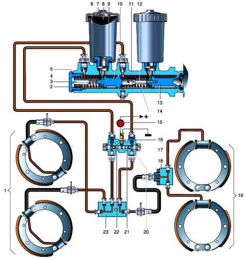
A variant of the brake system with a signaling device and separate tanks without a pressure regulator: 1 - front wheel brakes; 2, 14 - springs; 3 - emphasis; 4 - cork; 5 - gasket; 6 - tank; 7 - bank cover; 8 - grid; 9 - fitting; 10.13 - pistons; 11 - main cylinder body; 12 - stop screw; 15 - indicator lamp; 16 - signaling lamp switch; 17 - cork; 18 - tee; 19 - brake mechanisms of the rear wheels; 20 - housing of the signaling device; 21 - long piston; 22 - short piston; 23 - splitter
The pistons in the cylinder are arranged in series: the one closest to the vacuum booster actuates the brake mechanisms of the rear wheels, the other piston - the front ones
If there are no fluid leaks from the system, its level in the reservoir of the main brake cylinder should be between the MAX and MIN marks.
The level decreases as the brake pads wear
In the event of a violation of the tightness of the brake system and a drop in the fluid level in the tank, the sensor is triggered, and the indicator lamp on the instrument panel lights up.
In this case, add fluid only after the malfunction has been eliminated.
The vacuum booster is located between the pedal assembly and the main brake cylinder and is attached to the bracket with four studs
To increase the braking force, a vacuum is used in the intake pipe of the engine, to which the booster is connected by a hose.
The amplifier housing has an air filter that must be cleaned or replaced at least once a year.
When in If the amplifier fails, we replace it entirely.
The pressure regulator is attached to the cross member of the frame.
It adjusts the brake fluid pressure in the rear wheel brake circuit depending on the vehicle load, which reduces the likelihood of skidding when braking.
By monitoring rear axle loading through the load spring, it limits the fluid pressure in the rear brake circuit.
If the regulator fails, the entire regulator is replaced.
After replacing the adjuster or springs of the rear suspension, as well as the rear axle, it is necessary to adjust the position of the load spring relative to the rear axle
The alarm device is installed on some vehicles.
It serves to signal the loss of tightness in one of the circuits.
In this case, the indicator lamp on the instrument panel lights up.
Parking brake - manual, mechanical, transmission.
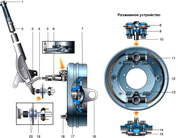
Parking brake system: 1 - lever button; 2 - lever; 3 - sector; 4 - thrust; 5 - lever; 6 - adjusting fork; 7 - brake drum; 8 - pusher; 9 - balls; 10 - body of balls; 11 - brake shoe; 12 - cup; 13 - coupling spring; 14 - expanding cracker; 15 - pad support; 16 - cardan eye; 17 - transfer case shaft; 18 - screw of the adjusting device; 19 - switch of the parking brake warning lamp; 20 - nuts
The force from the lever installed in the passenger compartment is transmitted to two blocks located inside the brake drum.
The drum is fixed with screws on the flange of the rear axle drive shaft of the transfer box.
Bleeding the brake system and changing the brake fluid
We bleed the brake system when air gets into it or the brake circuits are depressurized, when we replace brake cylinders, hoses, tubes, etc.
An assistant is needed to bleed the brakes.
This operation does not require an inspection ditch, a fairly clean, level area.
We clean the bleed valves from dirt.
Check the level of brake fluid in the reservoir (if necessary, add it to the MAX mark).
When pumping, we constantly monitor the level of brake fluid and add it, preventing the level from falling below the MIN mark.
Bleeding the brakes with the engine off and the rear axle loaded.
Remove the protective cap from the rear right wheel cylinder bleed valve and, putting on a transparent hose, immerse its free end in a container partially filled with brake fluid.
Depress the brake pedal 4-5 times.

Without releasing it, we unscrew the bleed valve by 1/3–1/2 turn with the “11” key.
Air bubbles will be visible in the liquid flowing from the hose.
After the pedal "goes" forward to the stop, squeezing a portion of the liquid from the system into the container, we wrap the valve and only then release the pedal.
Repeat pumping until air bubbles from the hose completely stop.
Having removed the hose, put a protective cap on the valve.
Then we bleed the brake cylinder of the rear left wheel.

We also bleed the pressure regulator

We pump the front wheel cylinders in the following sequence: lower right; upper right; lower left; top left.
If air remains in the system, then when you press the brake pedal, its elasticity will be felt.
In this case, repeat pumping until the pedal becomes "hard"
If bubbles continue to come out of the hose even after prolonged air removal, check the tightness of the connections, pipelines, hoses, main and working cylinders.
Tighten leaking connections, and replace faulty O-rings and cuffs of the master cylinder.
We replace the working cylinders as an assembly.
After bleeding, add fresh recommended brake fluid to the reservoir up to the MAX mark and install the reservoir cap with an emergency level drop sensor.
When changing the brake fluid, bleeding should be done before until fresh brake fluid (it is lighter) begins to exit the bleed valves of all working cylinders
Possible malfunctions of the brake system and methods of elimination
Increased brake pedal travel (pedal "fails")
- Increased gaps between pads and drums
Adjust the gaps between the shoes and drums, using only the adjusting eccentrics
If the pads are heavily worn (less than 0.5 mm remains to the rivet heads), replace them with new ones
When installing new pads or after replacing the pads, adjust both the adjusting eccentrics and the cams of the support pins
- Air ingress into the brake system due to: lack of fluid in the reservoirs of the main cylinder; brake fluid leaks in pipeline connections, cylinders, damage to pipelines, hoses, etc.
Pour liquid
Fix fluid leaks by replacing damaged parts if necessary
- Clogging of holes in the bosses of the covers of the reservoirs of the main cylinder
Clean the holes. After eliminating the cause of air ingress, bleed the system
Non-release (sticking) of the brakes
- There is no free play of the brake pedal
Adjust pedal freeplay
- Clogging of the compensation holes of the master cylinder
Clean the compensation holes and change the brake fluid if it is dirty
- Jamming of the pistons of the main or wheel cylinders
Replace cylinders
- Breakage of the brake pedal return spring
Replace spring
- Weakened or broken brake shoe return spring
Replace return spring
- Jamming pads on the bushings of the support pins
Clean and lubricate the bearing surfaces, taking care not to get grease on the brake pads
- Collapse of the pipeline, preventing the return of brake fluid from the wheel cylinder
Replace crumpled pipeline
Skid while braking
- Oiling the brake linings of one of the brakes
Remove the cause of overlay oiling. Replace pads or wash them in gasoline
- Loosening of the brake shield
Tighten the shield mounting bolts
- Different pressure in the tires of the right and left wheels
Readjust tire pressure to normal
- Loosening the tightening of the ladders of one of the springs
Tighten the ladder nuts
- Incorrect adjustment of the gap between the pads and the brake drum
Adjust Gap
- The pressure regulator does not work or the adjustment of the force of the elastic lever on the regulator piston is broken
Troubleshoot the regulator and its actuator. Adjust lever force
- Increased clearance between pads and drum
Adjust gap. If the friction linings are badly worn, then replace the linings or pads
Increased brake lever travel
- increased length of drive rod
Adjust drive rod length
Parking brake not working
- Jamming or corrosion of parts of the expander mechanism
Disassemble the expansion mechanism, wash and lubricate its parts
- Worn or oily lining pads
Remove the cause of overlay oiling. Replace pads or wash them in gasoline or kerosene
- incorrect adjustment of the gap or length of the rod
Adjust clearance or linkage length
Parking brake does not release
- Weakening or breakage of shoe coupling springs
Replace springs
- Jamming of the expanding mechanism
Disassemble the expansion mechanism, wash and lubricate the parts
- Incorrect adjustment of the clearance or length of the rod
Adjust clearance or linkage length

")
")
")
")
")
")
")
")