
Transfer box - two-stage, without center differential, with neutral gear and front axle disengagement
The transfer box consists of a cast-iron crankcase with a cover, which is attached to the rear wall of the gearbox through the holes in the base plate with four bolts.
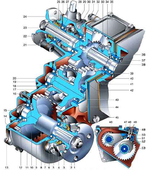
Distribution box: 1 - nut; 1 - flange of the front axle drive shaft; 3 - mud deflector; 4 - cuff; 5 - bearing cap; 6 - gasket; 7, 12 - front axle drive shaft bearings; 8 - front axle drive shaft; 9 - oil drain hole; 10 - front axle drive gear; 11 - crankcase; 13 - crankcase cover gasket; 14 - crankcase cover; 15 - bearing cover; 16 - cover gasket; 17 - front axle engagement gear; 18 - ball bearing of the intermediate shaft; 19 - bearing cover; 20 - intermediate shaft; 21 - oil slinger; 22 - cuff; 23 - rear axle drive shaft; 24 - flange of the rear axle drive shaft; 25 - bearing cover; 26 - gasket; 27, 31 - bearings of the rear axle drive shaft; 28 - axis of the parking brake lever; 29 - breather; 30 - speedometer drive gear; 32 - rear axle drive gear; 33 - splined crown of the drive gear; 34 - drive gear; 35 - hatch cover; 36 - gearbox housing; 37 - double-row ball bearing of the secondary shaft; 38 - secondary shaft of the gearbox; 39 - retaining ring; 40 - gaskets; 41 - base plate; 42 - intermediate downshift gear; 43 - intermediate shaft roller bearing; 44 - roller bearing plug; 45 - bolt; 46 - fork for switching on direct and downshifts; 47, 50 - fixed fork rods; 48 - control rods; 49 - control leads; 51 - ball; 52 - spring; 53 - front axle fork
The centering of the transfer case is provided by the outer ring of the double-row ball bearing of the secondary shaft of the gearbox.
The cover and crankcase are connected by bolts, fixed from displacement with two pins, and are replaced only as an assembly.
A parking brake mechanism is attached to the rear of the transfer case.
In the crankcase, the drive and intermediate shafts are placed on rolling bearings, as well as the drive shafts of the rear and front axles with spur gears.
The drive shaft is the splined end of the output shaft of the gearbox, on which the drive gear of the transfer case with spline is installed.
The rear axle drive shaft is mounted coaxially with the drive shaft on two ball bearings.
The speedometer drive helical gear is placed between the bearings.
The rear axle drive gear is integral with the shaft and has a splined hole inside.
The intermediate shaft rotates on roller (without inner ring) and ball bearings.
An intermediate downshift gear is made on the intermediate shaft and a front axle engagement gear is installed, sliding along the splines of the shaft.
The front axle drive shaft is integral with its gear and mounted in the lower part of the crankcase on two ball bearings.
On the splined ends of the axle drive shafts, cardan gear flanges are fixed.
At the top, the transfer case has a hatch closed with a lid.
The transfer box control mechanism consists of two rods with plugs installed in the cover.
The forks fit into the grooves of the drive gear and the front axle engaging gear.
The forks slide on fixed stems and have ball spring retainers inside.
Two control levers of the box are connected to the forks through movable stems and leashes.
Between these rods there is a blocking ball that prevents downshifting if the front axle is disabled.
The transfer case is lubricated with oil poured into the crankcase.
For filling and draining oil, there are two holes closed with plugs with conical threads.
The ends of the axle drive shafts are sealed with rubber cuffs, and the covers and crankcase hatch are sealed with paronite gaskets.
When direct gear is engaged, the drive gear moves back along the splines of the drive shaft until its spline ring enters the spline hole of the rear axle drive shaft gear.
Torque is transmitted directly from shaft to shaft and to the rear axle.
If at the same time the gear for engaging the front axle is shifted back along the splines of the intermediate shaft, it engages simultaneously with the gears of the drive shafts of the rear and front axles, which have the same number of teeth.
The axle drive shafts will rotate in the same direction at the same frequency, providing all-wheel drive of the vehicle.
When the front axle engagement gear is moved forward, the front axle is disengaged.
At the same time, the front engagement gear The axle disengages from the front axle drive gear, but remains engaged with the rear axle drive gear (wider).
The intermediate shaft rotates idle, providing oil splashing and lubrication of parts.
The front axle must not be engaged when the front wheel couplings are disengaged.
Do not engage the front axle when driving on dry paved roads.
This leads to accelerated wear of tires, transmission parts and increased fuel consumption.
To downshift, the pinion gear is moved forward until it meshes with the idler gear.
At the same time, the front axle engagement gear is necessarily engaged with the gears of the axle drive shafts, which is provided by the control mechanism.
The torque is transmitted through the drive gear to the intermediate shaft and then to both gears of the axle drive shafts.
Due to the fact that the intermediate gear is larger than the drive gear, and the gears of the axle drive shafts are larger than the gear for engaging the front axle, the transfer case works as a gearbox (gear ratio - 1.94 *) and the traction force on the drive wheels increases.
You can only downshift after the car has come to a complete stop.
When the drive gear is moved to the middle position, it does not engage with any of the gears and no torque is transmitted to the wheels (neutral gear).
A modernized transfer case with a smaller gear tooth module and a gear ratio reduced to 1.47 is installed on some cars.
It is fully interchangeable with the box of the previous design
Transfer boxes designed for installation with four- and five-speed gearboxes are not interchangeable
Changing the oil in the transfer case
We drain the oil from the transfer case immediately after the trip, while it is warmed up
It is best to change the oil at the same time in the gearbox and transfer case
We prepare the car and install it on a lift or a viewing ditch
We place a container under the drain hole

Unscrew the drain plug with a 12 hexagon and drain the oil into a container

If the used oil is dark in color or metal particles are visible in it, we wash the transfer case, for which we wrap the plug, cleaning its magnet from steel chips
The oil may have a dark color not only as a result of wear of parts, but also initially, for example, with the addition of molybdenum disulfide or graphite

Then, with a 12 hexagon, unscrew the filler plug
Pour about 0.5 l of a mixture of gear or engine oil (70–80%) with kerosene or diesel fuel (20–30%) into the box with an oil syringe and wrap the filler plug
Substituting stops under the bridges, we hang out one side of the car or the whole car.
Having switched on the first gear, we start the engine for 2–3 minutes.
Having installed the car on the wheels, completely drain the flushing oil (draining time is at least 5 minutes).
We clean the drain plug again and wrap it up

Having unscrewed the filler plug, use an oil syringe to fill the transfer case with gear oil (0.7 l)
We wrap the filler plug.
Check the oil level in the gearbox and top up if necessary
During operation, some of the oil may flow from the gearbox into the transfer case through the gearbox output shaft bearing. It is not necessary to equalize the oil levels in the units
Simultaneously with the oil change, we lubricate the axis of the transfer case control levers, for this:

We move the rubber boot on the levers up and with a syringe we inject any grease into the grease fitting of the axis of the levers
Possible malfunctions of the transfer case and methods of elimination
Increased noise in the transfer case
- Wear of gear teeth - crushing or chipping of working surfaces
Replace worn parts
- Loosening the nuts connecting the transfer case to the gearbox or the bolts securing the transfer case bearing caps
Tighten all bolts and nuts. If after that the noise does not stop, the transfer case should be disassembled and the malfunction repaired
- Bearing wear
Replace worn bearings
- Insufficient oil level or oil too thin
Change the oil (at the same time in the gearbox). After draining the oil, wash the crankcases of the gearbox and transfer case with a mixture of oil and kerosene
Difficulty shifting
- Unequal rolling radius of front and rear axle tires
Install tires with equal wear. Adjust tire pressure to recommended
- Jamming in the spline connection of the drive and intermediate shafts
Remove burrs, nicks, corrosion or replace parts. Lubricate the connection
- Nicks on the teeth of the small crown of the drive gear from impacts when turned on. Bent shift fork stem
Remove nicks and burrs, straighten the stem or replace parts
- Jamming of the shift levers on the axle
Disassemble the shift levers, flush the axle and lubrication channels. Lubricate and assemble levers with axle
Self disengagement of gear while driving or incomplete engagement of gears
- Bearing wear causing shaft misalignment
Replace worn bearings
- Increased clearance in the spline connection of the gear with the shaft
Tune the gear to the splines of the shaft to ensure a minimum clearance when moving freely along the splines
- Incomplete engagement of gears due to the curvature of the parts of the shift mechanism or nicks on the gears and splines
Straighten deformed parts or replace, clean nicks, ensure full fixed engagement of gears
- The work of the latch is weakened due to wear of parts or loss of spring elasticity
Replace worn parts
Oil leak
- Damage to the gaskets in the crankcase connectors, bearing caps and in the connection of the transfer case with the gearbox, loosening of the plug damper
Replace damaged gaskets, tighten plugs
- Loosening the nuts and bolts securing the bearing caps, the crankcase cover and connecting the transfer case to the gearbox
Tighten nuts and bolts at leaks
- Shaft seals worn or damaged
Replace cuffs
- Cracks in the crankcase
Replace crankcase
- Cracks or damage to the plugs of the shift rods or the plug of the intermediate shaft front bearing seat
Replace or emboss plugs in their sockets

")
")
")
")
")
")
")
")