
The anti-lock braking system (ABS) consists of wheel speed sensors, a switch on the brake pedal, a hydroelectronic control module and signaling devices in the instrument cluster
The anti-lock braking system includes EBD brake force distribution, ESP stability control (if equipped), and a self-diagnostic system that detects malfunctions of system components.
ABS is used to regulate the pressure in the brake mechanisms of all wheels when braking in difficult road conditions and thereby prevents the wheels from locking.
The ABS system provides the following benefits:
- – avoiding obstacles with a higher degree of safety, including during emergency braking;
- – reduction of the braking distance during emergency braking while maintaining roadholding and controllability of the car, including when cornering.
In the event of a system failure, diagnostics and maintenance functions are provided in case of system failures.

The hydroelectronic control module receives information about the vehicle speed, direction of travel and road conditions from the wheel speed sensors and the throttle position sensor.
After the ignition is turned on, the control unit energizes the wheel speed sensors, which use the Hall effect, they generate an output signal in the form of rectangular pulses.
The signal changes in proportion to the frequency of rotation of the encoder's pulse ring.
Based on this information, the control unit determines the optimal wheel braking mode.
The following modes of operation of the anti-lock braking system are distinguished:
– normal braking mode.
During normal braking, the intake valve is open, the exhaust valve is closed.
When you press the brake pedal, brake fluid under pressure is supplied to the working cylinder and actuates the wheel brakes.
When the brake pedal is released, the brake fluid returns to the brake master cylinder through the intake and check valves;
– emergency braking mode.
If the wheel locks up during emergency braking, the module issues a command to the pump motor to reduce the supply of brake fluid, then voltage is applied to each solenoid valve.
The intake valve closes and the brake fluid supply from the master cylinder and pump is shut off; the release valve opens, and the brake fluid flows from the working cylinder to the master cylinder, and then to the reservoir, which causes a decrease in pressure;
– pressure maintenance mode.
When the pressure in the working cylinder is reduced to the maximum, the module issues a command to maintain the brake fluid pressure, voltage is applied to the intake valve and not applied to the exhaust valve.
At the same time, the inlet and outlet valves are closed and the brake fluid does not leave the working cylinder;
– pressurization mode.
If the module determines that the wheel is not blocked, then the voltage is not applied to the solenoid valves, the brake fluid through the inlet valve enters the working cylinder, the pressure in which increases.
Special equipment and tooling are required for diagnosing and repairing the anti-lock brake system
Replacing the front wheel speed sensors

The front wheel sensor is installed in the rear knuckle hole
Disconnect the negative battery terminal
Remove the front wheel from the side of the work being done

We remove the front wheel liner, described in the article - Removing the fender liner and bumpers of a Hyundai Solaris car

Unscrew the bolt securing the front wheel speed sensor to the steering knuckle

Remove the sensor from the fist hole

Remove the speed sensor wire holder from the shock strut bracket

We unscrew the bolt that secures the sensor wire holder to the shock strut bracket

We unscrew the bolt securing the sensor wire holder to the body

Pry off the holder with a screwdriver

Remove the sensor harness holder

Press the lock of the front wheel speed sensor wire block

And disconnect the block

The front wheel rotation sensor harness block is located under the fender liner
When installing the front wheel speed sensor, align the hole in the sensor housing exactly with the threaded hole in the knuckle. During installation, do not rotate the sensor around the longitudinal axis.
An increase in resistance to the movement of the sensor should only be felt for the last 2 mm before it fully fits into the fist.
If the sensor with high resistance enters the knuckle hole from the very beginning of installation, remove the sensor and eliminate the cause of the binding (dirt, burr on the housing, etc.). It is strictly forbidden to press the wheel speed sensor with a hammer.
In the same way, remove the sensor on the other side
Install sensors in reverse order
Replacement of the rear wheel speed sensor
Disconnect the negative terminal from the battery
Remove the rear wheel, from the side of the task being performed
Remove the rear wheel liner

We unscrew the screw securing the wheel speed sensor

Remove the sensor from the brake caliper bracket hole
Remove the wiring harness from the clips on the rear suspension bracket and on the car body

Press the wire block retainer

Disconnect the rear wheel speed sensor wiring harness
Remove the rear wheel speed sensor
Installing the frequency sensor reverse order
Removing and installing ABS hydro-electronic unit

We remove the electronic engine control unit, as described in the article - Removing and checking the EMS sensors of a Hyundai Solaris car

Unscrew the battery shelf bolts

Remove the battery installation shelf

Squeeze the wire holder latch and remove the wire holder

Raise the clamp of the wire block and disconnect the block from the ABS control unit
Unscrew the tubes of the hydroelectronic block and plug the holes in the tubes and in the block

Remove the hydro-electronic unit from the engine compartment

Unscrew the screws securing the hydroelectronic unit to the bracket with a 5 hexagon
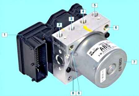
ABS unit: 1 - control unit; 2 - hole for connecting the tube of the brake mechanism of the right front wheel; 3 - hole for connecting the tube of the brake mechanism of the left rear wheel; 4 - hole for connecting the tube of the brake mechanism of the right rear wheel; 5 - hole for connecting the tube of the brake mechanism of the left front wheel; 6 - hole for connecting the tube of the main brake cylinder; 7 - pump; 8 - hydraulic modulator.
Install the hydro-electronic unit in reverse order

")
")
")
")
")
")
")
")